
METALLURGICAL AND MATERIALS TRANSACTIONS B VOLUME 28B, FEBRUARY 1997—47
Effect of FeO in the Slag and Silicon in the Metal
on the Desulfurization of Hot Metal
P.K. IWAMASA and R.J. FRUEHAN
Work has been conducted to investigate the effects of FeO in the slag and silicon in the metal on
hot metal desulfurization. Laboratory experimental results show that FeO decreases and silicon in-
creases the rate of desulfurization. Silicon in the metal is consumed by the reduction of FeO and
also by the desulfurization reaction. A mathematical kinetic model was developed to describe both
the effects of silicon and FeO on desulfurization for the laboratory scale. The model predicts the
sulfur and silicon content in the metal and the FeO and sulfur content in the slag as a function of
time. It is based on four-component simultaneous mass transfer: sulfur and silicon in the metal and
FeO and sulfur in the slag. Experimental results, the development of the kinetic model, and a com-
parison of the model and experimental results are presented.
I. INTRODUCTION
THE desulfurization of hot metal is a vital part of the
steelmaking process since sulfur in many steel products is
detrimental. In general, desulfurizing hot metal is more ec-
onomical than desulfurizing steel, and about 90 pct of the
metal produced in the iron blast furnace is desulfurized be-
fore it is sent to be processed in a steelmaking furnace. A
common practice is the injection of a desulfurizing reagent
through a lance. During injection, there are two sites at
which sulfur is removed from the metal. Sulfur is removed
by the reagent particles that are injected and rise in the
metal bath and also by the slag that accumulates at the top
of the metal. These reaction sites can be studied indepen-
dently and are referred to as the transitory (rising particles)
and the permanent contact (top slag) reactions. It has been
shown that when the same amount of slag is either simply
added to the top of the metal or injected, the sulfur content
of the metal reaches the equilibrium amount at about the
same time after the slag is introduced.
[1,2]
The present study
will focus only on the top slag reaction as results obtained
from these findings can be used to predict the behavior
during the injection desulfurization process. A subsequent
publication will utilize the basis of the model presented
here to demonstrate the effect of FeO in the slag and silicon
in the metal on desulfurization in actual industrial practice.
Although hot metal desulfurization is a mature process,
the effects of FeO in the slag have never been quantitatively
assessed. The FeO present in the desulfurizing unit origi-
nates from two main sources. The first source is slag carried
over from the iron blast furnace and the second is hot metal
oxidized during tapping from the blast furnace and during
transportation to the desulfurization station. The presence
of FeO in the slag during desulfurization hinders both the
thermodynamics and kinetics of the desulfurization process.
P.K. IWAMASA, formerly Graduate Student, Department of Materials
Science and Engineering, Carnegie Mellon University, is Research
Associate, BHP Research, New South Wales 2287, Australia. R.J.
FRUEHAN, Professor, is with the Department of Materials Science and
Engineering, Carnegie Mellon University, Pittsburgh, PA 15213.
Manuscript submitted October 5, 1995.
This can be demonstrated in the definition of the sulfur
partition ratio, L
S
, a measure of the thermodynamic ability
of a slag to contain sulfur.
[3]
(pct S) fC
SS
L 55 [1]
S
[pct S] hK
O2
where
(pct S) 5 weight percent of sulfur in the slag;
[pct S] 5 weight percent of sulfur in the metal;
f
S
5 activity coefficient of sulfur in metal relative to the
1 wt pct standard state;
C
S
5 sulfide capacity of the slag (as defined by Rich-
ardson and Withers
[5]
);
h
O
5 Oxygen potential of the system; and
K
2
5 equilibrium constant for the slag and gas equilib-
rium:
11
S (g) 1 O 5 O (g) 1 S [2]
22
22
FeO in the slag effects the sulfur partition ratio by con-
trolling the oxygen potential at the interface between the
slag and metal. This can be demonstrated by the chemical
equilibrium between FeO in the slag and the liquid iron and
the corresponding equilibrium constant expression:
(FeO) 5 Fe (I) 1 O [3]
ah
Fe O
K 5 [4]
3
i
a O
Fe
where
a 5 activity of liquid iron; and
Fe
i
a 5 activity of FeO in the slag at the interface.
FeO
By substituting Eq. [4] into Eq. [1], it can be seen that the
sulfur partition ratio is inversely proportional to the amount
of FeO in the slag at the interface for a fixed value of C
S
.
1
L
a
[5]
S
(pct FeO)
i
As the amount of FeO in the slag at the interface increases,
the thermodynamic ability of the slag to contain sulfur de-

48—VOLUME 28B, FEBRUARY 1997 METALLURGICAL AND MATERIALS TRANSACTIONS B
Fig. 1—Schematic of the experimental apparatus used for kinetic study.
creases for a fixed value of C
S
. In reality, C
S
may be a
function of FeO and S content, but this effect is small.
[4]
The aim of this work is to determine the kinetics of de-
sulfurization in the presence of silicon in the metal and
simultaneous reduction of FeO from lime (CaO) based slags
according to the following chemical reactions:
2S 1 2(CaO) 1 Si 5 2(CaS) 1 (SiO ) [6]
2
2(FeO) 1 Si 5 2Fe (I) 1 (SiO ) [7]
2
A mathematical kinetic model is also presented to describe
the time dependence of the concentration of silicon and
sulfur in the metal and FeO in the slag.
II. EXPERIMENTAL PROCEDURE
The experimental work included trials using 300 g of
metal and 30 g of slag of the following chemistry.
Metal: carbon saturated
0.12, 0.45 pct Si
0.14 pct S
master slag: 50 pct CaO
(premelted) 45 pct SiO2
5 pct MgO
slag addition: 0 to 5 pct FeO
Alloys, slags, and FeO used in the experiments carried out
in this study were prepared as follows.
Master Alloys. An Inductotherm induction furnace was
used to melt the metal alloys. Iron chips or lumps were
placed in a graphite crucible and melted. Silicon in the form
of ferro-silicon (50 pct Si) was added to the liquid metal
and allowed to equilibrate for a few minutes. Sulfur was
then added in the form of granular ferrous sulfide (FeS) and
allowed to equilibrate for another few minutes. The metal
was then cast into graphite crucibles (29-mm i.d., 50-mm
o.d., and 305-mm height) and left to cool overnight. Once
at room temperature, the resulting casting was cut, sand-
blasted, and ultrasonically cleaned to remove any surface
residue.
Slag. One kilogram of the mixture of reagent grade pow-
ders (50 pct CaO, 45 pct SiO
2
, 5 pct MgO) was mixed and
placed in a high density MgO crucible (96-mm i.d., 102-
mm o.d., and 152-mm height). The crucible was placed in
a Lindberg molybdenum disilicide resistance box furnace
and heated to a temperature of 1425 7C at a rate of 2 7C
per minute. The furnace was stabilized at 1425 7C for 30
minutes, the slag and crucible were furnace cooled, and the
slag was crushed.
FeO. FeO was prepared using a Lindberg silicon carbide
resistance tube furnace. About 100 g of reagent grade Fe
2
O
3
powder was placed in a steel crucible (39-mm i.d., 45-mm
o.d., and 128-mm height) and placed in the reaction tube.
The top was sealed and an alumina lance was placed
through the lid to about 1 cm from the powder surface. A
gas mixture of 50/50 CO/CO
2
was flowed through the lance
at a rate of 2 cc/s. The furnace was heated to a temperature
of 1150 7C and kept there for about 12 hours; it was then
cooled to about 800 7C. The gas atmosphere was changed
to argon for a 10-minute purge; then the cover of the fur-
nace was opened and the crucible removed and quenched
in a high flow rate of argon. X-ray diffraction analysis
showed that the end product was converted (more than 99
pct) to FeO.
A. Kinetic Experiments
Experiments were run using a 10 kW Ameritherm in-
duction furnace. A schematic of the apparatus is shown in
Figure 1. The metal was placed in a magnesia crucible (in-
side diameter 32 mm) and gradually heated to 1450 7C.
The experimental temperature was periodically measured
with an optical pyrometer. The chamber was closed to the
atmosphere and a low flow rate of argon (0.5 cc/s) was
maintained within the furnace during the experiment. A
graphite ring was used as a susceptor from the induction
field to heat the slag layer over the metal. The slag was
added by means of a funnel through the sample port, and
metal and slag samples were taken at varying times from
the time of slag addition. The metal samples were obtained
using silica suction tubes and the slag samples with notched
copper rods. The slag samples were chemically analyzed
for FeO (total iron, assumed to be in the form of FeO) by

METALLURGICAL AND MATERIALS TRANSACTIONS B VOLUME 28B, FEBRUARY 1997—49
Table I. Starting Composition of Slag and Metal for
Kinetic Experiments
Run
Identification [Pct S] [Pct Si] (Pct FeO)
S1 0.141 0.12 0.0
S2 0.143 0.12 5.0
S3 0.143 0.12 3.0
S4 0.143 0.12 1.0
S5 0.145 0.41 0.0
S6 0.144 0.43 5.0
S7 0.147 0.47 3.0
S8 0.147 0.44 1.0
Fig. 2—Effect of FeO on desulfurization: experimental results for metal
sulfur content as a function of time for initial slag FeO contents between
0 and 5 pct.
Fig. 3—FeO reduction: experimental results for slag FeO content as a
function of time for initial slag FeO contents between 1 and 5 pct.
redox titration with K
2
Cr
2
O
7
. The metal samples were an-
alyzed for carbon and sulfur using a LECO* Analyzer pro-
*LECO is a trademark of LECO Corporation, St. Joseph, MI.
vided by the AISI Pilot Plant (Universal, PA). Silicon con-
tents in the metal samples were determined using a wet
chemical technique at Spectrochemical Laboratories (Pitts-
burgh, PA).
B. Constant Volume Pressure Increase Experiments
Experiments utilizing the constant volume pressure in-
crease (CVPI) technique were carried out to investigate if
there was any gas evolution between the slag and metal
from experiments similar to those done in the induction
furnace. The motivation for these experiments was to jus-
tify the mass transfer coefficients that were fit to the math-
ematical model. These experiments were also used to prove
the assumption that the reduction of FeO in the slag by
carbon dissolved in the metal producing carbon monoxide
gas did not appreciably affect the mass balances used in
the development of the mathematical model.
A Lindberg silicon carbide resistance furnace was used
with a mullite reaction tube (48-mm i.d., 54-mm o.d., 610-
mm length, and closed round at bottom). An alumina ped-
estal was place at the bottom of the tube, and the MgO
crucible containing the metal was seated on the pedestal. A
mullite guiding tube (25-mm i.d., 32-mm o.d., and 457-mm
length) cemented (AREMCO* Cermabond 503) to the
*AREMCO is a trademark of Aremco Products, Inc., Ossining, NY.
MgO crucible extended through the length of the furnace.
The furnace was sealed and the temperature was slowly
increased from room temperature to 1450 7C under an ar-
gon atmosphere. Once 1450 7C was obtained, the argon
flow was stopped. Calibration of the equipment was carried
out by injecting a known volume of air into the furnace
and the response recorded by the data acquisition system.
Once the calibration was completed, a port in the lid was
opened and a pin sample was obtained. The slag was then
added and the port quickly sealed. The exit port of the lid
was connected to a pressure transducer (Daytronic 502)
which was connected to an analog to digital converter and
a data acquisition system. The data collected were in the
form of volts vs time, and volts were converted to moles
of gas using the calibration curve.
III. RESULTS
Table I outlines the starting composition of the slag and
metal for the experiments carried out in this series. The
normalized sulfur content of the metal as a function of time
is shown in Figure 2 for experiments S1 through S4. These
data clearly show the dependence of the desulfurization
ability of a slag as a function of the amount of FeO added
to the slag. In these experiments, the initial silicon content
of the metal is 0.12 pct Si. As the initial amount of FeO in
the slag increases, the desulfurization ability of the slag
decreases as does the rate of sulfur removal. Figure 3 shows
the concentration of FeO in the slag as a function of time.
For the results presented here, the initial silicon (0.12 pct
Si) and sulfur (0.14 pct S) contents were consistent. As seen
from this plot, FeO is reduced out of the slag rather quickly
and the equilibrium value for the concentration of FeO in
the slag is quite low.
Figure 4 displays the time dependence of silicon concen-
tration in the metal for the same series of experiments men-
tioned previously. As expected from the FeO reduction
reaction and the results for FeO content in the slag, as the
amount of FeO in the slag increases, more silicon is con-
sumed. Silicon is stoichiometrically consumed in both the

50—VOLUME 28B, FEBRUARY 1997 METALLURGICAL AND MATERIALS TRANSACTIONS B
Fig. 4—Silicon removal during desulfurization: experimental results for
metal silicon content as a function of time for initial slag FeO contents
between 0 and 5 pct.
desulfurization reaction and the FeO reduction reaction.
Mass balance calculations for silicon consumption for the
series of experiments, where the initial silicon content in
the metal is 0.12 pct, are presented in Table II. These cal-
culations are based on the initial and final values of the
constituents that were analyzed. As evident from the cal-
culations presented in Table II, the mass balances between
silicon in the metal are reasonable within a maximum 10
pct discrepancy. The contribution of silicon consumption
from FeO and sulfur varies depending on the initial FeO
content of the slag and is presented in Table III for the
same series of experiments.
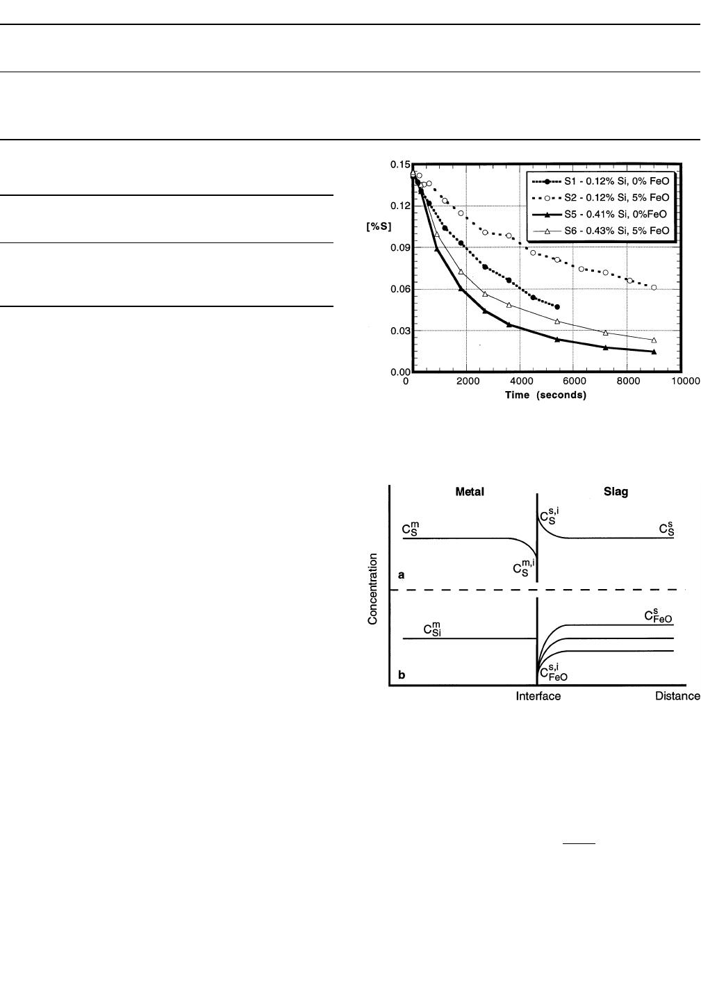
Figure 5 shows both the effects of FeO in the slag and
silicon in the metal on desulfurization. A greater silicon
content in the metal provides for better and more rapid
sulfur removal for both cases where the slag contains 5 pct
FeO and no FeO.
IV. MATHEMATICAL KINETIC MODEL
To better understand and analyze the results of the lab-
oratory experiments, a kinetic model was developed. This
section discusses the underlying assumptions that went into
the development of the mathematical model based on chem-
ical Reactions [6] and [7]. Sulfur, in the presence of silicon
in the metal, is removed by a lime based reagent, and FeO
in the slag is reduced by silicon in the metal. These as-
sumptions will be shown to be consistent with the experi-
mental results. The reduction of FeO in the slag by carbon
in the metal, as presented in the following chemical reac-
tion, is slow compared to the reaction between FeO and
silicon.
(FeO) 1 C 5 Fe (I) 1 CO (g) [8]
Reaction [8] was neglected in the mathematical model,
since it was determined to be relatively insignificant com-
pared to Reactions [6] and [7]. Previous investigators have
shown that Reaction [8] which involves three phases
(metal, slag, and gas) proceeds at a relatively slow rate by
means of gaseous intermediates.
[6,7,8]
It was found that for
a slag FeO content below about 2.5 pct, the rate is limited
by the chemical reaction rate at the gas/metal interface. For
slags with higher FeO contents, the reaction is controlled
by the kinetics of the chemical reaction at the slag/gas in-
terface. Kinetics of chemical reactions involving two phases
(slag and metal) are usually faster than three-phase reac-
tions. Typical slag/metal reactions are mass transfer con-
trolled in terms of elements diffusing through the slag and
the metal with very fast chemical kinetics at the interface.
The elimination of Reaction [8] in the mathematical model
is further discussed in the results for the CVPI experiments.
A. Assessment of All Possible Rate Controlling
Mechanisms
Before work on the model can commence, initial as-
sumptions about the controlling mechanisms to the preced-
ing reactions need to be made. There are many possible
rate controlling steps that may influence the reaction and
they are listed subsequently. It should be noted that com-
pounds in the slag phase diffuse as ions. For example, the
diffusing species for CaO are Ca
2+
and O
22
ions. However,
for charge neutrality, ‘‘CaO’’ can be considered as the
equivalent diffusing compound.
(1) Chemical reaction rate of Reference 6.
(2) Chemical reaction rate of Reference 7.
(3) Liquid-phase mass transfer of sulfur in the metal from
the bulk metal to the interface between the slag and
metal.
(4) Liquid-phase mass transfer of silicon in the metal from
the bulk metal to the interface between the slag and
metal.
(5) Liquid-phase mass transfer of CaO in the slag from the
bulk slag to the interface between the slag and metal.
(6) Liquid-phase mass transfer of ‘‘FeO’’ in the slag from
the bulk slag to the interface between the slag and
metal.
(7) Liquid-phase mass transfer of iron in the metal from
the interface between the slag and metal to the bulk
metal phase.
(8) Liquid-phase mass transfer of ‘‘SiO
2
’’ in the slag from
the interface between the slag and metal to the bulk
slag phase.
(9) Liquid-phase mass transfer of ‘‘CaS’’ in the slag from
the interface between the slag and metal to the bulk
slag phase.
B. Elimination of Possible Rate Controlling Mechanisms
To a first approximation, the chemical rates were as-
sumed to be fast, and the liquid phase mass transfers of
lime and silica in the slag are also assumed to be fast since
the slag composition is rich in both lime and silica which
results in a high driving force for mass transfer. As a par-
allel argument, liquid-phase mass transfer of iron in the
metal phase is taken to be fast. After elimination of the
previous mechanisms, the remaining possible rate control-
ling phenomena are the following:
(1) liquid-phase mass transfer of sulfur in the metal;
(2) liquid-phase mass transfer of silicon in the metal;
(3) liquid-phase mass transfer of ‘‘FeO’’ in the slag; and
(4) liquid-phase mass transfer of ‘‘CaS’’ or, more simply,
sulfur (S
22
) in the slag.
METALLURGICAL AND MATERIALS TRANSACTIONS B VOLUME 28B, FEBRUARY 1997—51
Table II. Mass Balance Calculations for Experiments S1 through S4
Run
Identification
Initial FeO
Content in the
Slag (Wt Pct)
Moles Silicon
Consumed (n
Si
)
Moles FeO
Reduced (n
FeO
)
Moles Sulfur
Lost (n
S
)
0.5 n
FeO
1 0.5 n
S
Difference between
(n
Si
) and
(0.5 n
FeO
1 0.5 n
S
)
S1 0 0.00471 0 0.00903 0.00452 1 5 pct
S2 5 0.01210 0.01920 0.00784 0.01350 210 pct
S3 3 0.01080 0.01200 0.00943 0.01070 1 1 pct
S4 1 0.00634 0.00316 0.00948 0.00632 1 0.3 pct
Table III. Relative Contribution to Silicon Consumption
for Experiments S1 through S4
Run
Identification
Initial FeO
Content in the
Slag (Wt Pct)
Pct Silicon
Consumed by
FeO Reduction
Pct Silicon
Consumed by
Desulfurization
S1 0 0 100
S257129
S335644
S412575
Fig. 5—Effect of FeO and silicon on desulfurization: experimental results
for metal sulfur content as a function of time for initial slag FeO contents
of 0 and 5 pct and initial silicon contents of 0.12 and 0.41/0.43 pct Si.
Fig. 6—Schematic concentration profile of elements in the slag and metal
phases near the interface: (a) sulfur in the metal and slag; and (b) silicon
in the metal and FeO in the slag based on mass transfer of FeO in the
slag.
The model is based upon the four mechanisms presented
earlier, and because the reactions are mass transfer con-
trolled, the flux of these elements and species at any given
time during the process can be defined as follows:
mmmm,i
J 5 mC2 C [9]
SS
~
SS
!
mmmm,i
J 5 mC2 C [10]
Si Si
~
Si Si
!
S S S S,i
J 5 mC2 C [11]
FeO FeO
~
FeO FeO
!
S S S,i S
J 5 mC
2
C [12]
SS
~
SS
!
where
5 flux of A in phase (slag or metal) b (moles cm
22b
J
A
s
21
);
5 mass transfer coefficient of A in phase b (cm s
21
);
b
m
A
5 concentration of A in bulk b phase (moles cm
23
);
b
C
A
and
5 concentration of A in the b phase at the interface
b,i
C
A
between the slag and metal (moles cm
23
).
C. Sulfur Mass Transfer
The mass transfer behavior of sulfur is well known and
has been extensively studied. It has been found that, in
general, it is the simultaneous mass transfer of sulfur in the
metal and sulfur in the slag that controls sulfur removal
from metal. This is represented by equating the sulfur fluxes
( ) and is schematically displayed in Figure 6(a).
ms
J 5 J
SS
mm m,iSs,iS
m (C 2 C ) 5 m (C 2 C ) [13]
SS S SS S
In Eq. [13], the surface concentrations of sulfur in the slag
and metal are related to each other by the sulfur partition
ratio. In the model, the concentration of sulfur in the slag
and metal are continually changing and the sulfur partition
ratio is defined at each time-step. The mass transfer of sul-
fur in the metal phase can be rewritten to include the mass
transfer of sulfur in the slag phase:
S
C
r
S m
mm
J 5 mC2 [14]
S0S
~!
L
r
S s
where
r
m
5 density of metal (g cm
23
);
r
s
5 density of slag (g cm
23
);
m
0
5 time-dependent overall mass-transfer coefficient for
sulfur in the metal:
52—VOLUME 28B, FEBRUARY 1997 METALLURGICAL AND MATERIALS TRANSACTIONS B
Fig. 7—Schematic concentration profile of elements in the slag and metal
phases near the interface: (a) silicon in the metal and FeO in the slag
based on mass transfer of silicon in the metal; and (b) silicon in the metal
and FeO in the slag based on simultaneous mass transfer of FeO in the
slag and silicon in the metal.
ms
mmL
r
SSSs
~!
r
m
m 5 [15]
0
s
mL
r
SSs
m
1 m
S
~!
r
m
For most desulfurizing slags (for instance, lime-rich slags),
the sulfur partition ratio L
S
is quite large, on the order of
10
2
to 10
4
. In those limiting cases, the overall mass transfer
coefficient for sulfur (m
0
) will reduce simply to the mass
transfer coefficient for sulfur in the metal ( ). Since FeO
m
m
S
in the slag was being reduced and silicon in the metal was
being oxidized, the concentration gradient of FeO and sil-
icon would affect the interfacial conditions for sulfur trans-
fer. Therefore, the coupled sulfur mass transfers in the slag
and metal were ruled out as the only two rate controlling
mechanisms.
D. Mass Transfer of FeO in the Slag
The mass transfer of FeO from the bulk slag to the in-
terface between the slag and metal was the next mechanism
considered. Because of the ionic nature of the slag, a more
accurate description of FeO transfer is the mass transfer of
Fe
2+
and O
22
ions. Since mass transfer will depend on the
slower of the two ions, namely, O
22
, it should be an ac-
ceptable assumption to consider the mass transfer of the
compound itself. A simplified way to conceptualize FeO
transfer is to look at a schematic of the concentration pro-
files of FeO in the slag and silicon in the metal, as shown
in Figure 6(b).
If the rate is controlled only by mass transfer of FeO in
the slag, the driving force for FeO reduction is proportional
to the difference between the concentration of FeO in the
bulk slag and the concentration of FeO at the interface
( ). The concentration of FeO at the interface is
ss,i
C 2 C
FeO FeO
in equilibrium with the silicon in the metal. This means that
for a constant silicon content, is a low, constant value
s, i
C
FeO
and is independent of the bulk FeO concentration. The ox-
ygen potential at the interface is defined by the equilibrium
between FeO at the interface and the iron in the metal.
Also, the sulfur partition ratio is inversely proportional to
the interfacial concentration of FeO. The sulfur partition
ratio would then be a constant value, independent of the
FeO content of the bulk slag. Based on the results of the
experiments, desulfurization behavior was dependent on the
bulk FeO content in the slag so mass transfer of FeO in the
slag was ruled out as the sole rate controlling step.
E. Mass Transfer of Silicon in the Metal
The mass transfer of silicon from the bulk slag to the
interface between the slag and metal is examined next. This
is shown schematically in Figure 7(a). If the mass transfer
of silicon in the metal is the sole rate controlling step, the
driving force for silicon oxidation is proportional to the
difference between the bulk and interfacial concentration of
silicon in the metal, ( ). The concentration of sil-
mm,i
C 2 C
Si Si
icon at the interface is a low and constant value and sets
the oxygen potential for desulfurization. In this case, the
sulfur partition ratio is inversely proportional to the inter-
facial concentration of silicon which is set by the equilib-
rium between the slag and the metal at the interface and
independent of the silicon content of the bulk metal. Based
on the experimental results, desulfurization is dependent on
the bulk silicon content of the metal, and mass transfer of
silicon in the metal is ruled out as the sole rate controlling
step.
F. Model Basis: Flux Equations
Sulfur transfer in the metal and slag, mass transfer of
FeO in the slag, and mass transfer of silicon in the metal
considered separately were eliminated as the individual rate
controlling steps for the reactions kinetics. Therefore, the
model is developed utilizing dynamic simultaneous mass
transfer of sulfur in the slag, sulfur in the metal, silicon in
the metal, and FeO in the slag. Based on the stoichiometry
for chemical Reactions [6] and [7], the balance of the mass
fluxes between silicon in the metal with FeO in the slag
and sulfur in the metal at any time during the process is
represented as
ms m
2 J 5 J 1 J [16]
Si FeO S
A schematic of the overall process of combined FeO and
silicon diffusion is shown in Figure 7(b).
These assumptions do not provide for a priori knowledge
of the dependency of the sulfur partition ratio, since the
interfacial concentrations of silicon in the metal and FeO
in the slag are in equilibrium and are no way related to the
bulk concentrations. The interfacial concentrations of sili-
con in the metal and FeO in the slag are related by the
equilibrium constant for chemical Reaction [7]. Therefore,
the mathematical model is based on the preceding flux
equations and the sulfur balance Eq. [14], which are solved
simultaneously at each time-step.
G. Mass Transfer Coefficients
Since the experiments were inductively stirred, the mass
transfer coefficient for sulfur and FeO in the slag and sulfur
and silicon in the metal can be related to one another based
on the relationship presented by Higbie.
[9]
1/2
4Dv
m 5 [17]
~!
p
r

METALLURGICAL AND MATERIALS TRANSACTIONS B VOLUME 28B, FEBRUARY 1997—53
Table IV. Diffusion Data for Sulfur and Silicon in Carbon
Saturated Iron at 1450 7C
Diffusing
Element
Concentration
(Wt Pct) D (cm
2
/s) Reference
S ,0.64 3.13 3 10
25
10
S — 3.09 3 10
25
11
Si — 2.20 3 10
25
11
Table V. Diffusion Data for Sulfur and Oxygen in Slags at
1450 7C
Diffusing
Element
Slag
Composition
(Wt Pct) D (cm
2
/s) Reference
40CaO
O
[17]
40SiO
2
6.17 3 10
2612
20Al
2
O
3
40CaO
O
[18]
40SiO
2
7.76 3 10
2612
20Al
2
O
3
38CaO
O 42SiO
2
7.5 3 10
2613
20Al
2
O
3
50.6CaO
S 39SiO
2
7.13 3 10
2714
10.4Al
2
O
3
40.8CaO
40.8SiO
2
S 51Al
2
O
3
6.65 3 10
2715
3FeO
0.4S
where
m 5 mass transfer coefficient (cm s
21
);
D 5 diffusivity (cm
2
s
21
);
v 5 surface velocity (cm s
21
); and
r 5 radius of the crucible (cm).
Diffusion data for sulfur and silicon in carbon saturated
iron and relevant components in example slags as presented
in the literature are summarized in Tables IV and V. Based
on average values obtained for the diffusivity of sulfur and
silicon in the metal as presented in Table IV and the ratios
of the square roots of the diffusivities, the relationship be-
tween the mass transfer for the elements in the metal phase
was taken to be
mm
m 5 1.2 m [18]
SSi
Likewise for the slag phases, the following relationship was
made based on the data presented in Table V:
ss
m 5 0.31 m [19]
SFeO
In the model, the values used for and were deter-
ms
mm
Si FeO
mined from the experimental data and were not derived
from first principles. The values for and were cal-
ms
mm
SS
culated from the input values for and by Eqs. [18]
ms
mm
Si FeO
and [19]. Therefore, the model only has two adjustable
mass transfer parameters, one for the slag and one for the
metal.
H. Governing Flux Equation
The governing dynamic mass transfer flux equation, an
expansion of Eq. [16], is represented as follows:
s
C
r
S m
m m m,i s s s,i m
2 m (C 2 C ) 5 m (C 2 C)
1
m (C 2 ) [20]
Si Si Si FeO FeO FeO 0 S
L
r
S s
Equation [20] is based on Eq. [16], which assumes silicon
is consumed by FeO reduction and the desulfurization re-
action.
I. Interfacial Concentration of FeO in the Slag
The interfacial concentration of FeO in the slag is defined
in terms of the interfacial concentration of silicon in the
metal using the equilibrium constant for chemical Reaction
[7] and is solved at each time-step.
2
2
aa
100 nMW
Fe SiO
s FeO
2
K 5 [21]
7
ii2 i,2
~!
f [pct Si]
g
(pct FeO) W
Si FeO s
where
a
Fe
5 activity of liquid iron;
5 activity of silica in the slag;a
SiO
2
5 activity coefficient of silicon in the metal at the
i
f
Si
slag/metal interface with respect to the 1 wt pct standard
state;
[pct Si]
i
5 interfacial silicon concentration in the metal
(wt pct);
(pct FeO)
i
5 interfacial FeO concentration in the slag
(wt pct);
g
FeO
5 activity coefficient for FeO in the slag
W
s
5 slag weight (g); and
n
s
5 number of moles in the slag.
The interfacial concentration of FeO in the slag can be
expressed as
1/2
1
i
(pct FeO) 5 G [22]
FeO
i
~!
[pct Si]
where
1/2
2
aa
100 nMW
Fe SiO
s FeO
2
G 5 [23]
FeO
i 2
~!~ !
f
g
KW
Si FeO 7 s
J. Oxygen Potential at the Slag Metal Interface
The interfacial oxygen potential is defined by the time-
dependent equilibrium between silica in the slag and silicon
in the metal. Because of the interfacial equilibrium condi-
tions between the constituents in chemical Reaction [7], the
oxygen potential defined by the equilibrium between silica
in the slag and silicon in the metal will be identical to the
oxygen potential defined by FeO in the slag and the liquid
iron. Therefore, the following reaction is at equilibrium at
the slag/metal interface:
Si 1 2O 5 (SiO ) [24]
2
The equilibrium constant of this reaction is
a
SiO
2
K 5 [25]
24
ii2
f [pct Si] (h )
Si O
54—VOLUME 28B, FEBRUARY 1997 METALLURGICAL AND MATERIALS TRANSACTIONS B
Fig. 8—Experimental data and model results for metal sulfur contents as
a function of time for experiment S5. Initial experimental conditions:
0.145 [pct S], 0.41 [pct Si], and 0 (pct FeO).
The oxygen potential at the slag/metal interface is defined
by
1/2
ii
f [pct Si] K
Si 24
h 5 [26]
O
~!
a
SiO
2
K. Sulfide Capacity of the Slag
Besides the oxygen potential of the system, the sulfide
capacity of the slag, C
S
, must be known to calculate the
sulfur partition ratio. In this model, the sulfide capacity
used is taken from the data originally generated by Ka-
lyanram et al. for a slag of similar composition to the one
used in the experiments.
[16]
Kalyanram et al. made meas-
urements at 1500 7C, so a temperature correction for the
temperature of the experiments used in this study (1450 7C)
was taken from work carried out by Nassaralla et al.
[17]
The
value used for the sulfide capacity in this study was 9.33
3 10
24
, which was found to be consistent with the average
sulfide capacities computed from the final experimental val-
ues for the experiments that were assumed to reach equi-
librium.
For example, in experiment S6, the sulfur partition ratio
calculated by mass balance of sulfur at the end of the ex-
periment was L
S
5 52.6. The final FeO content in the slag
equaled 0.13 pct FeO. The oxygen potential was based on
the final FeO content in the slag and the activity of liquid
iron in the metal. Based on Eq. [1], the sulfide capacity was
determined to be 9.4 3 10
24
. The value used for C
S
was
taken to be constant for the duration of the experiment since
the bulk slag composition did not appreciably change. For
the model, the sulfur partition ratio was calculated (Eq. [1])
based on the oxygen potential of the system and the sulfide
capacity of the slag, and the sulfur flux equation was
solved.
L. Interfacial Concentration of Silicon in the Metal
The overall flux equation which is solved at each time-
step is recast in terms of the interfacial concentration of
silicon in the metal:
s
m
r
MW
FeO s Si
i
[pct Si] 5 [pct Si] 2
m
~!~ !
MW 2 m
r
FeO Si m
1/2
1
(pct FeO) 2 G [27]
FeO
i
~~!!
[pct Si]
m
r
MW (pct S)
0 m Si
2 [pct S] 2
m
~!~ !~ !
MW 2 m
r
L
SSim S
As presented in Eq. [27], [pct Si]
i
is not a simple algebraic
expression and is solved by a numeric iteration technique.
The interfacial silicon content in the metal is solved and is
used as the basis for solving for the interfacial concentra-
tions of the FeO in the slag. These values are solved at
each time-step and then the flux equations
[9–12]
are solved.
A computer program was written in THINK Pascal for
the MACINTOSH* for this kinetic model. In this program,
*MACINTOSH is a trademark of Apple Computers, Inc., Cupertino,
CA.
the process variables of the system are read as input (tem-
perature, slag and metal weight, and composition). The only
other input variables in the program are the mass transfer
parameters for FeO in the slag and silicon in the metal. The
program output consists of the following bulk and interfa-
cial concentrations as a function of time: sulfur in slag,
sulfur in the metal, FeO in slag, and silicon in metal.
V. DISCUSSION
A. Kinetic Experiments
The mathematical model developed was utilized to ana-
lyze the results of the small scale experiments. In this anal-
ysis, the model is fit to the experimental results by
obtaining the ‘‘best-fit’’ values for the mass transfer coef-
ficients ( and ). The mass transfer coefficients used
ms
mm
Si FeO
in the model which best fit the experimental data are
m
m
Si
5 0.003 cm s
21
m
m
FeO
5 0.002 cm s
21
In experiments carried out in similar types of induction fur-
naces, the mass transfer coefficient is normally somewhat
larger than was observed in this study. This may be due to
the graphite ring consuming the bulk of the induction cou-
pling and the surface velocity at the interface between the
slag and metal not being as high as in the previous work
where no graphite ring was used. The importance of the
surface velocity at the slag/metal interface to determine the
mass transfer coefficient in an inductively stirred melt was
presented in Eq. [17]. Another contribution to this low mass
transfer coefficient as related to the velocity at the interface
of the slag and metal is the resistance that the slag provides
for flow. Also, it would be expected from the diffusivity
data that the value of would be about half of , and
sm
mm
FeO Si
this is about what was observed. Actually, was greater
s
m
FeO
than half of , and this could be attributed to the evolution
m
m
Si
of gas at the interface between the slag and the metal. This
is discussed later in detail.
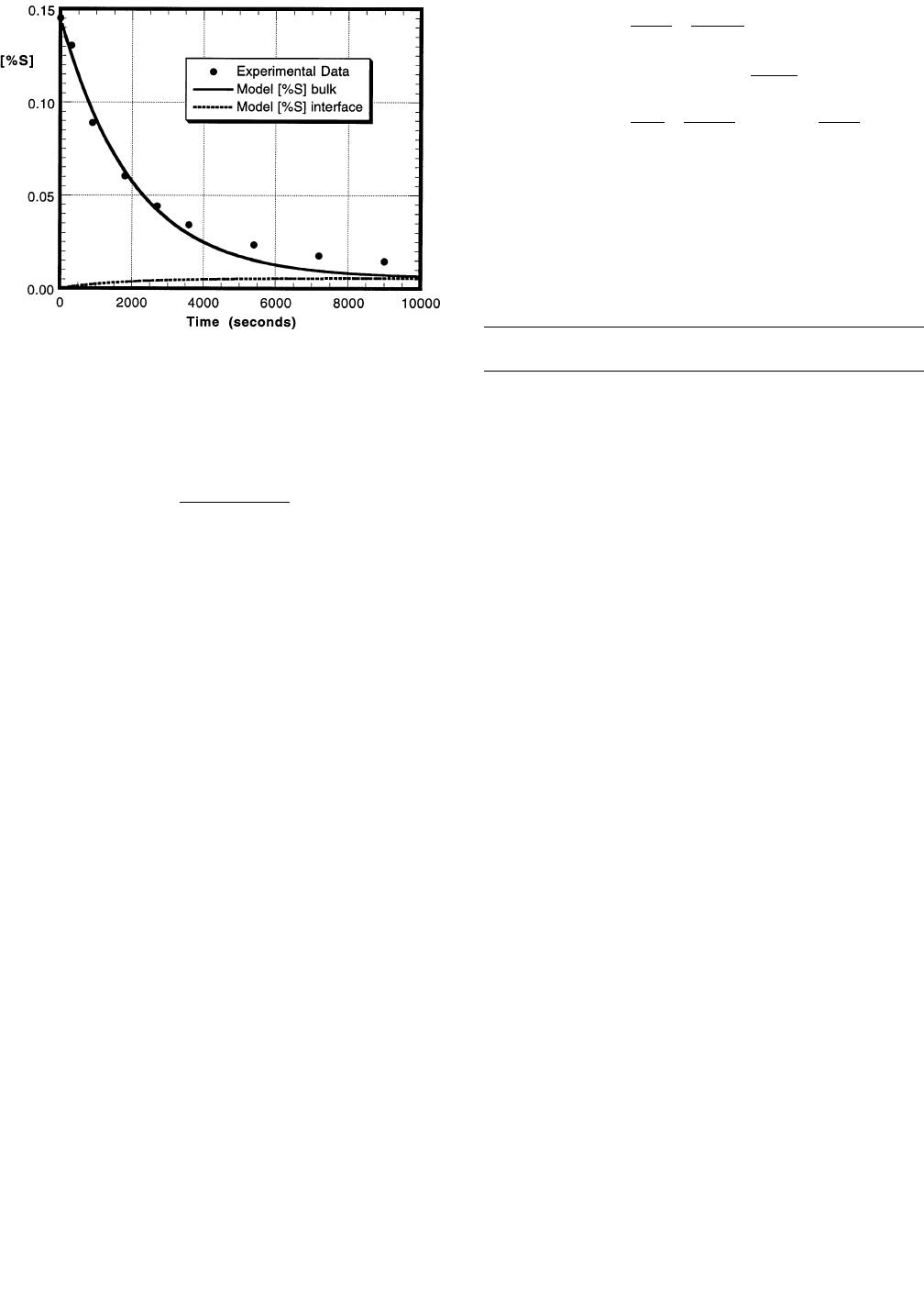
Figures 8 and 9 display the experimental results and the
kinetic model output for the sulfur and silicon contents in
the metal for experiment S5, where no FeO was added to
the slag. Since there was no FeO present in the slag, only
the desulfurization reaction (chemical Reaction [6]) was
METALLURGICAL AND MATERIALS TRANSACTIONS B VOLUME 28B, FEBRUARY 1997—55
Fig. 9—Experimental data and model results for metal silicon content as
a function of time for experiment S5. Initial experimental conditions:
0.145 [pct S], 0.41 [pct Si], and 0 (pct FeO).
Fig. 10—Experimental data and model results for metal sulfur content as
a function of time for experiment S7. Initial experimental conditions:
0.147 [pct S], 0.47 [pct Si], and 3 (pct FeO).
Fig. 11—Experimental data and model results for metal silicon content as
a function of time for experiment S7. Initial experimental conditions:
0.147 [pct S], 0.47 [pct Si], and 3 (pct FeO).
Fig. 12—Experimental data and model results for slag FeO content as a
function of time for experiment S7. Initial experimental conditions: 0.147
[pct S], 0.47 [pct Si], and 3 (pct FeO).
considered in this case, where the moles of silicon lost from
the metal is twice the moles of sulfur lost from the metal.
The agreement between the experimental data and the
model results is quite good for the sulfur profile but not as
good for the silicon. As seen from these figures, the inter-
facial (equilibrium) concentrations of sulfur and silicon are
plotted along with their respective bulk concentrations. It
can be seen that as the reaction proceeds, the bulk concen-
trations tend to the equilibrium concentrations, as expected.
There is a reasonable fit of the experimental results with
the calculated values obtained from the mathematical
model. Since this simplified case utilizes both the metal and
slag mass transfer coefficients, it can be assumed that the
values used for and are reasonable and should be
ms
mm
SS
used in the case where FeO is present in the slag. In the
experiments where FeO is present in the slag, it is difficult
to compare the model results with the experimental data
since the starting amount of FeO in the slag is not known
accurately. Experimentally, the FeO powder is added to the
master slag when it is at room temperature and mechani-
cally mixed. This ‘‘cold’’ slag is then introduced to the
metal melt which is at 1450 7C, and the starting time for
the desulfurization of the metal is defined as this point. The
problem inherent in this method is the fact that the slag
does not melt instantaneously as assumed. From visual in-
spection of the procession of the experiments, it takes a few
minutes for the slag to melt and cover the metal surface.
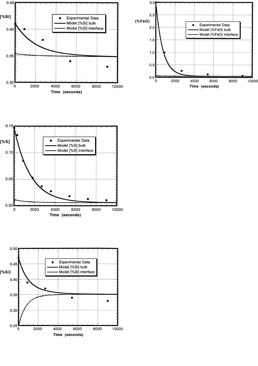
Figures 10 through 12 display the experimental data and
model predictions for the results of experiment S7, where
the initial cold amount of FeO in the slag is 3 pct and the
initial silicon content in the metal is 0.47 pct. Figure 10
shows the amount of sulfur in the metal as a function of
time as compared to the bulk concentration predicted from
the model. Also, the interfacial concentration of sulfur in
the metal is shown in this plot. Figure 11 displays the sil-
icon content in the metal vs time, and Figure 12 shows the
amount of FeO in the slag vs time. The model was run with
the initial amount of FeO in the slag as 3 pct. The plots
display that equilibrium is obtained near the end of the
experiment, about 8000 seconds after the slag is added to
the melt, when the bulk concentration profiles and interfa-
cial concentration profiles merge. The experimental data
56—VOLUME 28B, FEBRUARY 1997 METALLURGICAL AND MATERIALS TRANSACTIONS B
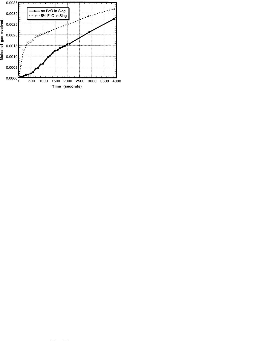
Fig. 13—Experimental results for CVPI experiments comparing the moles
of gas evolved for experiments where there was 0 or 5 pct FeO in the
slag.
and the model predictions fit reasonably well. Similar
agreement between the experimental results and model pre-
dictions were obtained with the other slag FeO contents and
metal silicon contents.
Based on the experimental data and the results obtained
from the model, the basis of the mathematical model seems
to be viable. The presence of FeO in the slag does affect
desulfurization of hot metal, and as the amount of FeO in
the slag increases, the desulfurization rate decreases and the
equilibrium sulfur content in the metal increases. Silicon in
the metal is stoichiometrically consumed by two reactions:
the desulfurization reaction and reduction of FeO from the
slag.
B. CVPI Experiments
Experiments were carried out to investigate if there was
any evolution of gas from reactions between the slag and
metal for the kinetic experiments. Based on the diffusivity
data presented, it is expected that the mass transfer coeffi-
cients for elements in the slag phase should be about half
of those in the metal phase for the case where there is a
stagnant slag metal interface. (The diffusivity of oxygen in
the slag is about a factor of 4 less than the diffusivity of
silicon in the metal, and they are related by the square root
of the diffusivity). Since it was found that the mass transfer
coefficients for the slag used in the kinetic model were
comparatively greater than expected, it was proposed that
there may be some evolution of gas at the interface between
the slag and metal that would increase the mixing in the
slag phase and promote better mass transfer kinetics.
Results from these experiments with 0 and 5 pct FeO in
the slag are presented in Figure 13 for metal initially con-
taining 0.17 pct silicon and 0.19 pct sulfur. The results
show that there is some gas evolution during the experi-
ments. It may be surprising that gas is produced in the
experiments, where FeO is not present in the slag, but it
has been found that the following chemical reaction may
take place at the slag/metal interface:
[7]
(SiO ) 1 2C 5 Si 1 2CO (g) [28]
2
Exit gas from some of these experiments was analyzed us-
ing a mass spectrometer (Dycor M100 Quadrupole Gas An-
alyzer), and it was found that the gas that evolved was
primarily CO with some CO
2
. The balance of the gas pro-
duced in the experiments where FeO was present in the
slag was assumed to be from the chemical reaction men-
tioned previously.
This amount of gas evolved was assumed to be enough
to provide for an increased mass transfer over the stagnant
case, but not a significant amount to account for it in the
mass balances for the model. The total amount of FeO that
is consumed by carbon in the metal (the difference of these
two plots) is determined to be about 5 pct of the total
amount of FeO in the slag that is reduced. This would sig-
nify that the bulk (95 pct) of the FeO is reduced by silicon
in the metal and would not significantly alter the mass bal-
ances assumed in the model.
For the experiment where no FeO was present in the slag,
about 0.0027 moles of CO (g) were produced throughout
the duration of the experiment. This amount of gas corre-
sponds to 0.00135 moles of silica that are reduced (Eq.
[28]), which equals about 7 pct of the total initial silicon
content in the metal. Therefore, the amount of silicon in
the metal available for desulfurization may actually be a
little higher than expected. There may also be experimental
reasons for measuring an increase in pressure in these ex-
periments that are independent of any reaction between the
slag and metal. These reasons include the initial heating
and melting of the slag and shifting of the reaction tube as
it was sealed. Like carbon reduction of FeO, it was assumed
that this 7 pct increase in the silicon content was insignif-
icant in the model mass balances.
A subsequent publication will include a scale up and ex-
pansion of this kinetic model to include desulfurization as
pertaining to the AISI Direct Steelmaking process. Also,
submerged injection of the desulfurizer will be incorporated
in the model to describe the industrial hot metal desulfur-
ization process.
VI. CONCLUSIONS
Experiments with carbon saturated iron containing sili-
con and sulfur and a slag of nominal composition 50 pct
CaO, 45 pct SiO2, and 5 pct MgO, with additions of FeO,
were carried out in this study. A mathematical kinetic
model was developed to predict sulfur, silicon, and FeO
transfer to describe the results of the laboratory experi-
ments. The results from the laboratory experiments and the
model show the following.
1. As FeO in the slag decreases, the desulfurization rate
increases and the final sulfur equilibrium content in the
metal is lowered. The oxygen potential at the interface
between the slag and metal is lower with lower FeO
contents in the slag, which increases the sulfur partition
ratio.
2. Greater desulfurization results as the amount of silicon
in the metal is increased. Higher contents of silicon in
the metal provide for a lower equilibrium FeO content
in the slag at the slag metal interface and a greater driv-
ing force for FeO reduction from the slag. This also
increases the sulfur partition ratio of the slag.
