
New Techniques for Damage Assessment
of Diesel Particulate Filters
Tim Hands and Qiang Li
Abstract The maximum soot load capacity for ceramic Diesel Particulate Filters
(DPFs) is sometimes limited by a thermal crack failure mechanism associated with
high temperature gradients which can occur during regeneration of highly loaded
parts—particularly at low exhaust flow rates. The filter material and construction
can be optimised for resistance to thermal cracking, however, the precise condi-
tions which give rise to thermal failure of DPFs can be difficult to establish
accurately and repeatably. For instance, thermal failure of DPFs may occur at the
onset of the heating due to the exotherm of trapped soot, or during cooling (for
instance at the fuel cut during deceleration or start of idle). The time of occurrence
of thermal failure can help to establish the worst conditions for filters. Sectioning
parts post-test is often conducted to establish the nature and location of any
damage. However non-destructive testing allows for the possibility of progressive
testing of single parts—allowing determination of the ‘Soot Mass Limit’. Post-test
scanning techniques have been demonstrated (e.g. X-Ray/CT scanning). These
allow non-destructive testing, but are generally expensive, and require the DPF to
be removed from the can. This paper describes important considerations for
application of two existing post-test evaluations as follows. (1) Radial and axial
ultrasound ‘Time-of-flight’ measurement. (2) Internal imaging of the DPF with a
small borescope. Also presented are two novel non-destructive techniques for
assessing damage to DPFs as follows. (1) An in situ technique capable of mea-
suring filter vibration events during DPF operation which may be associated with
F2012-A04-006
T. Hands
Cambustion Ltd, Cambridge, UK
e-mail: [email protected]
Q. Li (&)
Cambustion China Office, Shanghai, China
SAE-China and FISITA (eds.), Proceedings of the FISITA 2012 World
Automotive Congress, Lecture Notes in Electrical Engineering 189,
DOI: 10.1007/978-3-642-33841-0_47, Ó Springer-Verlag Berlin Heidelberg 2013
609
thermal crack damage. A surface microphone coupled directly to the filter sub-
strate through a hole in the can and intumescent matting measures brick vibration,
while a background detector measures exhaust pipe and canning vibration events
in order to discriminate metallic thermal expansion. Vibration and internal ther-
mocouple data is presented from exothermic regenerations for several different
filters loaded with soot on a commercial Diesel Particulate Generator with standard
Diesel fuel and fuel treated with a catalytic additive. The extension of the tech-
nique to testing on a vehicle is demonstrated. (2) A relatively simple, post-test
evaluation which involves reverse aspiration of DPF test parts with a cold Diesel
soot aerosol generated with compressed air. The technique can locate DPF cells
where the soot aerosol is not filtered though the substrate between the inlet and
outlet channels. The deposition of soot on the substrate is shown to be an indicator
of internal damage and, together with simple optical microscopy, can help to
identify failure mechanisms. The paper presents examples of the above techniques
to examine thermal damage to Silicon Carbide and Aluminium Titanate DPFs
which have been subject to ‘worst case’ regenerations.
Keywords DPF
Crack
SML
DPG
Diesel
1 Introduction
The regeneration of heavily loaded Diesel Particulate Filters (DPF) parts can cause
thermal damage to DPF substrates due to the high thermal gradients associated
with the exothermic oxidation of the deposited soot.
The threshold of thermal damage depends on the physical properties of the DPF
material used—including: thermal conductivity, heat capacity, material strength
(fracture toughness K
Ic
), Coefficient of Thermal Expansion (CTE), Young’s
modulus (E), melting point/maximum application temperature. Further, the
application of a catalytic coating to the DPF or addition of a fuel borne catalyst can
significantly affect the threshold of exothermic reaction.
Most wall flow DPFs fall into two categories as follows:
Monolith These have a single brick construction and are usually made from
Cordierite.
Segmented For vehicle applications, these are typically made from individual
segments which are cemented together. They are usually made from
Silicon Carbide.
The differences in the physical and thermal properties of these filter types leads
to significant differences in thermal damage resistance (usually associated with
loaded regeneration).
610 T. Hands and Q. Li
1.1 Damage Assessment
An important part of Soot Mass Limit Testing is the method by which a part is
determined to be damaged.
1.1.1 Filtration Performance
Concerning the degradation in the filtration performance of a part, the assessment
of filtration should be made on a DPF part which is loaded from clean, since the
filtration performance is a strong function of the soot loaded onto the part at small
soot loads. Further, for small cracks, the accumulation of soot on the part can
‘bridge’ or plug the cracks and restore filtration performance. This behaviour of
soot can be observed in Figs. 1 and 2.
Figure 2 shows the change in soot mass filtration efficiency following Soot
Mass Limit tests of increasing severity with soot load measured with an AVL415S
smoke meter.
Some workers have adopted the criterion for damage to a part to be a reduction
in filtration efficiency of more than one percent at a total accumulated soot load of
0.5 g. By this criterion, the data in Fig. 2 indicates that the Soot Mass Limit for
this part is between base load (6 g soot/l) and base load +15 % (6.9 g soot/l).
1.1.2 Mechanical Integrity
Although DPFs may leak due to missing end plugs or manufacturing faults, the
cause of the degradation in filtration performance is generally due to internal
cracks. Computerised Tomography using X rays can produce images of internal
cracks (see Fig. 3).
However, this technique is relatively expensive and requires the DPF to be
removed from its can. This paper describes alternative techniques to identify
damaged parts.
Fig. 1 TEM pictures of soot loading onto a DPF from clean (from [9])
New Techniques for Damage Assessment of Diesel Particulate Filters 611
2 Instrumentation
2.1 Existing Post-Test Evaluation Techniques
This section discusses two techniques which can only be conducted post-test, when
the sample is cooled and with reasonable access to the rear face of the DPF.
DPF Filtration Efficiency
50
55
60
65
70
75
80
85
90
95
100
0 0.1 0.2 0.3 0.4 0.5 0.6
0.7
0.8 0.9 1
Soot Load (g)
Filtration Efficiency %
De-greened part
Base load
Base + 15%
Base + 30%
Fail
Fig. 2 Mass-based filtration efficiency of a DPF as a function of total soot load
Fig. 3 CT image of radial
crack in SiC DPF from [1]
612 T. Hands and Q. Li
2.1.1 Ultrasound Time of Flight Measurement
The technique of non-destructive inspection of rigid materials via Acoustic
Emission (AE) is well established [2]. Recently, it has been applied to alternative
materials including asphalt [3] and ceramic monoliths [4, 5].
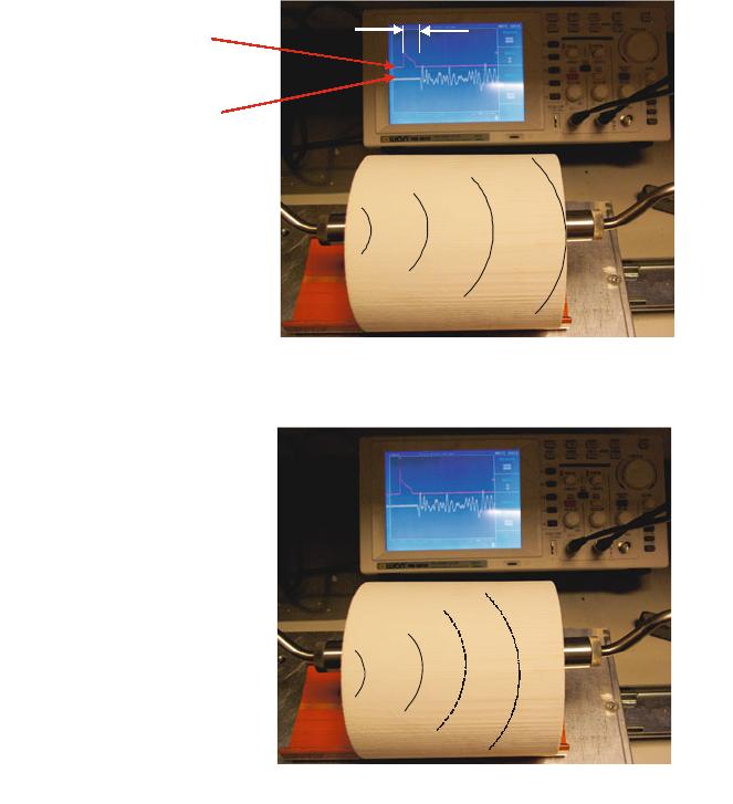
‘Time of flight’ measurements were made using a Pundit plus Model PC1006.
The system uses a separate ultrasound emitter and detector and measures the
transit time through the substrate. The experimental arrangement is shown in
Figs. 4 and 5 for an ‘intact’ and damaged DPF respectively.
The figures above illustrate how a radial crack significantly attenuates and
delays the detected signal. If the part is not canned (as shown in the figures), it is
also possible to make radial measurements (across diameters of the DPF).
Emitter
signal
Detector
signal
‘Time of flight’ ~ 40us
For ‘Intact’ DPF
Fig. 4 Axial ultrasound measurement ‘intact’ DPF
‘Time of flight’ ~ ?
For cracked DPF
(Detector signal very
attentuated)
Fig. 5 Axial ultrasound measurement damaged DPF
New Techniques for Damage Assessment of Diesel Particulate Filters 613
When making these measurements, the following considerations are important:
1. The coupling of the emitter and detector to the surface of the DPF has a strong
effect on the detected signal. We have found that Blu-tack [6] with a thickness
of *2 mm gives good and repeatable acoustic coupling for the detector and
emitter.
2. The compressive force by which the emitter and detector are coupled to the
DPF also has a strong effect on the detected signal (a high compressive force
can tend to close cracks which tends to reduce transit times and generally
increase the energy in the transmitted signal). In order to obtain repeatable
results, a mechanical arrangement which keeps this force constant is required.
2.1.2 Internal Borescope Inspection
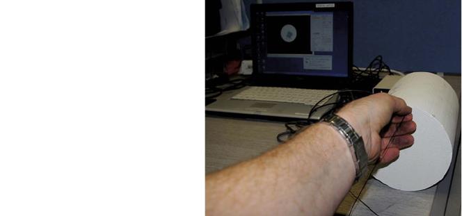
Some workers have used a small diameter borescope (e.g. [7]) to inspect individual
cells of a DPF. In order for the technique to work well, the part should be loaded
with a small amount of soot. The optical fibre bundle (*0.5 mm diameter) is
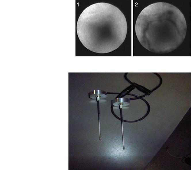
inserted down the exit cell of a DPF with suspected crack as shown in Fig. 6.
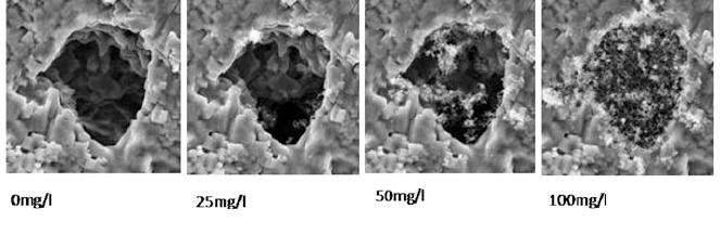
As the fibre is traversed along the length of the cell, where the cell walls are
intact, there is no evidence of soot (see image 1 in Fig. 7). However, a cracked cell
allows soot through from the inlet side of the DPF and a black line is observed (see
image 2 in Fig. 7).
Note that this technique is most sensitive where there is good contrast between
the DPF substrate and the soot (it is more difficult to locate cracks in SiC parts—
which are generally dark grey).
Fig. 6 Borescope inserted
into exit cells of DPF
614 T. Hands and Q. Li
2.2 Novel evaluation techniques
2.2.1 In-situ: Custom Vibration Detectors
During ‘worst case’ regenerations of loaded DPFs on a burner-based DPF testing
system (Cambustion DPG [8]) it was noted that damage to DPFs was associated
with audible cracks. These were distinct from the metallic creaks associated with
the rapid heating of the exhaust pipe and DPF can.
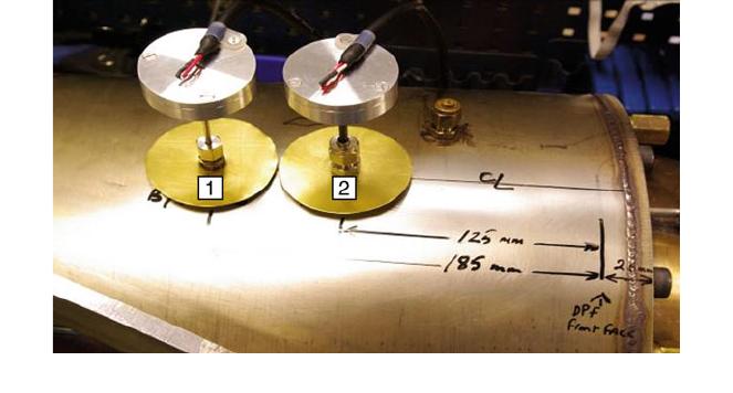
Custom surface microphones were developed where the microphone diaphragm
is remote from the DPF substrate, but coupled to it via a rigid rod. These are shown
in Fig. 8 and installed on a DPF test housing in Fig. 9.
The background sensor rod is coupled directly to the DPF can and responds
primarily to vibration ‘events’ associated with the exhaust pipe and DPF can. The
DPF crack sensor (2) in Fig. 9 is located in a stainless steel guide tube and the tip
is resting directly onto the surface of the DPF (a small hole is cut in the intu-
mescent matting to allow this). It responds primarily to vibration ‘events’ from the
DPF itself.
Fig. 7 Images of intact
channel (1) and damaged
channel (2)
Fig. 8 Custom surface
microphones with coupling
rods
New Techniques for Damage Assessment of Diesel Particulate Filters 615
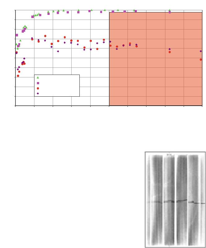
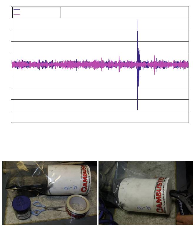
The raw vibration signals from these microphones are high-pass filtered in order
to accentuate the events associated with cracks. The high-pass filtered signals are
then monitored to produce a second by second output of DPF and background
crack activity.
2.2.2 Post Test: Reverse Soot Aspiration
A damaged DPF part can provide a transit path for soot through a crack rather than
through the wall of the filter. If a highly concentrated soot aerosol is blown through
a DPF (from entry to exit), the portion of aerosol travelling through the walls of the
DPF will be filtered and therefore no soot will arrive at the exit face. For a
damaged part however, soot can travel from the entry face to the exit face without
being filtered.
Some workers use a smoke aerosol and laser sheet on the entry face to observe
this ‘leakage’. An alternative novel technique conducted on a clean, cold DPF is
illustrated below.
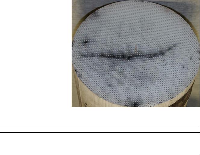
1. A sample of Diesel soot (typically several grams) is placed into a polythene bag
which is sealed around the entry face of the DPF (upper picture).
2. Clean compressed air is blown backwards through the DPF (from exit to entry)
creating a jet of air at the entry. This jet stirs the Diesel soot and creates a
highly concentrated aerosol which then travels through the DPF (from entry to
exit)—with a total flow rate similar to the compressed air jet.
3. As the air jet is moved over the surface of the suspect DPF, all cells of the DPF
are exposed to highly concentrated Diesel aerosol (lower picture) (Figs 10, 11).
Where a part is damaged, the soot exiting the front face of the DPF via cracks
leaves a black deposit. Figure 12 shows a part after reverse aspiration. Missing/
Fig. 9 Background (1) and DPF (2) crack sensors installed on DPF can
616 T. Hands and Q. Li
damaged plugs are evident at the bottom and top left of the image and a crack
across the part is also evident.
Note that this technique is also most sensitive where there is good contrast
between the DPF substrate and the soot (it is more difficult to locate cracks in SiC
parts—which are generally dark grey).
Filtered vibration sensor
-0.05
-0.04
-0.03
-0.02
-0.01
0
0.01
0.02
0.03
0.04
0.05
350.95 350.97 350.99 351.01 351.03 351.05
Time (s)
Crack sensor filtered
Can sensor filtered
Fig. 10 DPF crack (blue) and can (pink) sensors filtered response to single brick crack
Fig. 11 Reverse aspiration of DPFs with soot aerosol
New Techniques for Damage Assessment of Diesel Particulate Filters 617
3 Test Program
Two Passenger car DPFs were tested as follows:
1. SiC uncoated 5.66
00
9 10
00
.
2. Aluminium Titanate uncoated 5.66
00
9 8
00
.
These parts were successively loaded to higher and higher soot loads and
regenerated with a ‘worst case’ regeneration (heated to *700C inlet at 63 kg/hr,
overall lean) whilst being continually monitored for cracks. The tests are sum-
marised in Table 1.
The parts were instrumented with internal 0.5 mm thermocouples inserted from
the rear face in order to resolve the temperature field during the regeneration
(Table 3).
4 Results
4.1 SiC In Situ Crack Data
See Figs. 13–15.
Fig. 12 Crack and missing/
damaged cell plugs
Table 1 DPF test program
Soot load (g/l) SiC 5.66 9 10
00
AT 5.66 9 8
00
8 4 (with Eolys fbc) 4
12 4 (with Eolys fbc) 4 (with and without Eolys fbc)
15 4
618 T. Hands and Q. Li
