Requirements on Organic Electro-Optic Devices for Aerospace
Applications
W. W. Anderson, S. P. Ermer, T. E. Van Eck, D. G. Girton, R. E. Taylor
Lockheed Martin Advanced Technology Center
Palo Alto, CA 94304
ABSTRACT
Terrestrial digital photonic technology development will not satisfy all of the
aerospace requirements since RF links are often required. Organic electro-optic devices
are readily adaptable to RF functions into the 100 GHz and above frequency range. In
addition to lossless links, they can be utilized for RF signal processing functions such as
mixing, efficient harmonic generation and filtering. Devices can be densely packed with
negligible cross talk.
In addition to the well known survivability requirements for space born applications
(lifetime, reliability, thermal, shock, vibration and radiation hardness), issues of weight
and power become dominant. Organic devices based on thin film technologies have an
obvious potential advantage with respect to weight. However, integration with other
optical and/or electronic components needs to be considered since connectors often
dominated size and weight. Performance (when translated back into the electronic
domain) scales as the optical power and device sensitivity squared. Thus, advances in
device sensitivity can be nullified by increases in optical loss.
INTRODUCTION
The potential generic benefits of photonics technology in aerospace applications
have been recognized for many years. These potential benefits include lightweight and
small size of the transmission medium (optical fiber and/or free space), immunity to
electromagnetic interference (including EMP), low on-board (spacecraft or aircraft)
transmission loss and practically unlimited bandwidth. Actually, the real trade, which is
usually made, is the cost associated with the architecture that meets the system
performance requirements. In aerospace applications, the cost drivers are size, weight and
raw power.
The terrestrial commercial telecommunications market has seen the rapid
development of digital photonics technology to accommodate an apparently insatiable
demand for bandwidth or information capacity. Much of this technology can be adapted
and/or qualified for aircraft or space borne use when required (due to high data rate
functionality) or desired (due to cost advantage).
The aerospace industry is almost unique in requiring broadband RF systems in
addition to digital systems. (The only other industry with broadband RF distribution
requirements that the author can think of is the Cable TV industry and there is movement
in that industry towards digital distribution.) The aerospace RF links and applications are
up-down and cross platform communications, broadband radar and electronic warfare. In
addition to the free space portion of the links, there is typically an on-board RF
distribution system between the antenna (in the wing of an aircraft or out-board on a space
platform) and the RF processor in the body of the vehicle. This distribution system may
require fiber because of weight considerations (vis à vis coax or waveguide), low loss,
broad bandwidths, phase stability or EMI mitigation.
Electro-optic polymer photonic devices are particularly attractive for very high
frequency and broadband applications since the basic electro-optic interaction involves an
intra molecular electronic transition. Even mm-waves are essentially “low frequency”
compared to the fundamental chromophore resonance in the visible portion of the
spectrum. Electro-optic device performance has been demonstrated up to 113 GHz
1
. This
high frequency and broadband capability is of particular interest given the 17.8-21.2 GHz
and 25.25-31.3 GHz mobile, broadcast and fixed satellite services bands and the 37.0 GHz
and higher all satellite services including ISL bands. Polymer devices are implemented
with thin film technology that has the capability of hybridization onto Si, GaAs, ceramic
or flexible
2
substrates. For space applications, they are expected to exhibit minimal
ionizing radiation damage cross section since they mainly consist of thin layers of the light
elements H, C, N and O. Finally, there is a significant development potential for devices
with RF gain, low noise figure, low power operation and signal processing functions such
as frequency conversion and efficient harmonic generation.
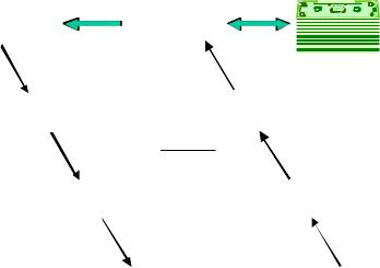
POLYMER PHOTONICS
The “customer” for polymer photonic components is ultimately a system supplier
who is only concerned about performance and cost. The performance issues that the
system supplier may be concerned with at the subsystem level for the RF portions of the
system are parameters such as gain (G), noise figure (NF), intermodulation products (IP2
and IP3), cross talk, electromagnetic interference (EMI), etc. At the material end of the
“food chain” shown in Figure 1 are such material properties as refractive index (n),
dielectric constant (ε
r
), density, spectral absorptance (α) and, for non-linear optical (NLO)
active electro-optic materials, the molecular properties of hyperpolarizability (β) and
dipole moment (µ). As we work our way up the food chain, the material processing
associated with orienting the molecular dipole moments results in a bulk material property
described by the electro-optic coefficient (r
mn
) which is a function of β, the number
density of NLO molecules (N) and their effective orientation (<cos
3
θ>). The orienting
process (“poling”) may also change α of the bulk material (by a little understood
Figure 1. The language of Figures-of-Merit
G∝1/V
š
2
NF∝V
š
2
V
š
=
λh
n
3
r
33
L
r
33
=Nβ<cos
3
θ>
Gain (G)
Noise Figure (NF)
Half-Wave
Voltage (Vš)
Electro-Optic
Coefficient (r
33
)
Hyperpolarizability (β)
Dipole Moment (µ)
RF Subsystem
Parameters
Photonic Component
Parameter
Bulk Material
Parameter
Microscopic Molecular
Parameters

phenomenon called “poling induced loss”). The device engineer will then utilize the NLO
material in the fabrication of a modulator such as the Mach-Zehnder modulator
3
(MZM)
whose performance may be characterized by its sensitivity (V
π
), insertion loss (η
opt
), and
bandwidth (BW). The sensitivity, V
π
, shown in Figure 1, is determined by the material
parameters n and r
33
as well as the device dimensions
3
h and L and the optical wavelength,
λ. The insertion loss will be given by η
opt
=η
i
η
o
e
-αL
(where η
i
is the input coupling loss
and η
o
is the output coupling loss). The bandwidth will be limited by
BW = c 4(n− ε
eff
)L (where c is the velocity of light and the effective dielectric
constant (ε
eff
) is determined by ε
r
and the dimensions of the RF electrodes
3
).
PHOTONIC LINK PERFORMANCE
The system engineer is only concerned about the contents inside the dotted box of
Figure 2 insofar as they effect the transfer of RF power between input and output,
P
RFo
/P
RFi
, and the size, weight, power and cost of the contents of the box. The critical
performance parameters of available gain (G
A
) and NF are given by:
G
A
=
P
opt
η
opt
A
r
2
π
V
π
2
r
i
r
o
4
= I
D
π
V
π
2
r
i
r
o
4
(1)
and
NF =1+δ+
1
G
A
+
<i
RIN
2
>+< i
shot
2
>
G4kT
(2)
where P
opt
is the input laser power to the link, A
R
is the photodetector responsivity , k is
Boltzmann’s constant and T is temperature. The currents in Eqns. (1) and (2) are the
average DC photocurrent, I
D
(given by I
D
=P
opt
opt
A
R
/2 as implied by Eqn. (1)), the laser
source relative intensity noise (given in terms of an equivalent mean squared noise current
<i
RIN
2
>=RIN•I
D
2
) and the photodetector shot noise (given in terms of an equivalent mean
squared noise current <i
shot
2
>=2eI
D
). The relative intensity noise (RIN) scales with I
D
2
as
does G
A
. RIN noise can be minimized either by use of a low RIN coefficient laser source
or by use of a balanced MZM output and balanced photodetector. The δ term in Eqn. 2
may be given by δ=r
s
/r
i
at low frequencies where r
s
is the RF source internal resistance or
by δ=0 at high frequencies for a source matched to the characteristic impedance of a
travelling wave RF structure which is velocity matched to the optical signal. Assuming
Figure 2. Basic photonic link
L
• •
Input coupl ing
loss, η
i
Output co upling
loss, η
o
P
Oi
P
Oo
P
RFi
P
RFo
r
o
r
i

Figure 3. RF gain and noise figure of a photonic link.
RIN noise negligible in a balanced modulator and δ≈0, we can plot the gain and noise
figure as a function of I
D
and V
π
as shown in Figure 3. From Eqns. (1) and (2) or Figure 3
it is apparent that modulator sensitivity, V
π
, and detected photocurrent (optical power) are
equally important in providing an RF link with gain (or at least without loss). For NF
reduction, depending on the modulator sensitivity, there will always be a regime of
decreasing incremental improvement with photocurrent (optical power) at high
photocurrent levels. A polymer modulator sensitivity of V
π
=0.8 volts has recently been
reported
4
utilizing a push-pull polymer poling scheme
5
. Further material and processing
improvements are expected to further improve modulator sensitivities to V
π
<0.3 volts.
However a more significant system payoff can now be achieved by reducing the optical
insertion loss!
THE LOSS ISSUE
Modulator insertion loss determines power requirements of the photonic link as well
as achievable performance parameters.
From Eqn. (1), it is apparent that link gain is a monotonically increasing function of
optical power input, (P
opt
). Spacecraft power is expensive and the conversion of raw
power to optical power is typically 5 to 15% efficient. Each 3 dB increase required in
optical power to achieve a required photocurrent level results in a doubling of raw power
required. In addition, since uncooled laser diodes are currently limited to about 10 mW, a
higher laser power may require active cooling which results in added weight and power.
If we insert the length dependencies of optical loss and modulator sensitivity into the
gain expression, Eqn. (1), we find that
G
A
=
P
opt
η
opt
A
r
2
π
V
π
2
r
i
r
o
4
∝ P
opt
e
−αL
L
( )
2
(3)
so that the maximum achievable gain is obtained at a modulator interaction length of
L=1/α. For the guest-host electro-optic polymer shown in Figure 4, the absorption
minima of 1.6 dB/cm (α=.38 cm
-1
) at λ=1.55 µm and 2.5 dB/cm (α=.58 cm
-1
) at λ=1.3 µm
fix the optimum lengths at L=2.6 cm or L=1.7 cm for the two principal telecom-
munications wavelengths. Note that at the optimum lengths for maximum gain, the
absorption loss will be 4.3 dB which may be unacceptably high if optical power is at a
premium.
Gain, G (dB)
- 2 0
- 1 5
- 1 0
- 5
0
5
1 0
1 5
2 0
0 . 0 0 1 0 . 0 1
Average Detected Photocurrent (A)
V
š
=.2
V
š
=.5
V
š
=1
V
š
=2
V
š
=5
Noise Figure, NF (dB)
0
5
10
15
20
25
30
0 . 0 0 1 0 .0 1
š
š
Average Detected Photocurrent (A)
V
š
=.2
V
š
=.5
V
š
=1
V
š
=2
V
š
=5
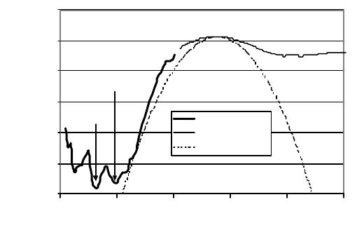
Figure 4. Photothermal deflection spectroscopy of a chromophore in a polycarbonate.
There are two inherent sources of optical loss from the material shown in Figure 4.
The peaks and valleys in the 0.5 < hυ < 1.0 eV spectral regime are due to overtones of C-
H stretching modes while the low energy tail of the chromophore fundamental absorption
band may be responsible for some of the loss at 1.3 µm. In most of the guest-host systems
we have investigated, the 1.3 µm minimum is lower than the 1.55 µm minimum
6
.
However, in those systems, the chromophore absorption peak is blue shifted compared to
the example in Figure 4. Intrinsic material absorption will set a lower limit on the loss
mitigation in any device design. Since C-H stretching mode overtones are expected to set
a lower limit to current generation optical loss, we plan to take advantage in the current
effort to reduce plastic optical fiber losses by the replacement of C-H bonds with C-F
7
.
OTHER PERFORMANCE ISSUES
While gain, noise figure and power consumption are basic requirements, other
performance requirements such as bias point stability, high optical power induced
degradation and operational lifetime are equally important for aerospace applications.
The issue of bias point stability for electro-optic polymer modulators has been
identified as due to differing dielectric relaxation time constants associated with the
constituent layers of the modulator
8
. If the bias point of a modulator drifts with time, it is
necessary to include an active bias control circuit to maintain the operating point at an
optimum as determined by operational requirements such as a minimum composite second
order distortion point.
To obtain an average detected photocurrent of I
D
=.01 A for the low NF regime of
Figure 3 may require optical input powers the order of 100 mW (assuming A
R
=.8 A/W,
αL=1 and η
i
=η
o
=−1 dB). For typical optical waveguide dimensions in a modulator of 5
µm x 2 µm, the optical power density will then be 1 MW/cm
2
. While some NLO polymer
materials are known to degrade at these power densities
9
, crosslinked polymer materials
10
have been shown to be stable at .9 MW/cm
2
.
1 .E+ 0 0
1 .E+ 0 1
1 .E+ 0 2
1 .E+ 0 3
1 .E+ 0 4
1 .E+ 0 5
1 .E+ 0 6
0 . 5 1 1 . 5 2 2 .5 3
Photon Energy (eV)
Absorption (dB/cm)
1.3 µm
1.5 µm
PDS data
UV-vis calib.
Gaussian fit
The operational lifetime of aerospace components and subsystems should be at least
15 years. The longest running evaluation of a polymer modulator
11
the author is aware of
is 8 years during which time the performance degraded only 25%.
SPACE ENVIRONMENTAL ISSUES
Components to be used in satellites must be qualified for space application. Some
of the specific qualification requirements are based on the particular mission such as Low
Earth Orbit exposure to rapid thermal cycling as it passes in and out of the earth’s shadow,
Medium Earth Orbit exposure to radiation in the Van Allen Belts and some military
missions which must survive a nucelar event. The environmental stress may be
accentuated or ameliorated depending on the location of the component such as in the bus
where it will be shielded or outboard on an antenna where it will be directly exposed to the
space environment. While the detailed qualification requirements will vary, they will all
consist of some level of (1) random vibration, (2) shock (G-force vs. frequency), (3)
thermal vacuum, (4) temperature cycling (many cycles of slow ramp and soak), (5)
thermal shock (many cycles of fast temperature ramping), (5) radiation, (6) EMI and (7)
out-gassing.
Since polymer electro-optic devices are basically thin film structures on robust
substrates, the shock and vibration issues are mainly packaging. In particular, if
modulators, sources, switches, isolators, detectors, etc. are to be interconnected, then
optical alignment and dimensional stability are the potential weak points rather than the
intrinsic device structure.
The poling process is carried out at elevated temperatures (ca. the glass transition
temperature of the host polymer) and then frozen in as the temperature is reduced. The
resultant structure is metastable at operating temperature and high temperature excursions
can result in loss of poling order. Therefore, these devices will only be appropriate where
the thermal excursions do not result in depoling.
We have subjected an early polymer modulator structure to gamma and proton
radiation as a preliminary evaluation of radiation hardness. No change in modulator
sensitivity nor optical loss was observed at gamma exposures up to 5 Mrad(Si) or to
proton exposures up to 500 kRad(Si)
12
THE COST ISSUE
Polymers are of interest for passive integrated optical waveguide circuits
13
and
electro-optically active polymers are of interest for EO modulators
3
. Since these
components or devices are fabricated from thin films of polymer material using (mostly)
standard integrated circuit process equipment, the limiting high volume production cost is
expected to be minimal. However this observation is conditioned by two considerations,
the reality of a high volume market and the component cost compared to other system
costs. For spacecraft applications, a significant component or subsystem cost is the space
qualification process. Component and subsystem costs then contribute to launch costs
through size, weight and power requirements.
The use of photonic technology for supporting large phased array antennas has been
extensively investigated over the past decade due to the potential providing time delay
without bulky, heavy and lossy transmission lines and the subsequent reduction in weight,
volume, and cost
14
. A recent study considered the economic viability of an airborne

phased array structure consisting of ca. 36 sub-arrays, each of which contained 32
individually addressed elements
15
. The individually addressed element count was thus
1152 and each element required a 2 GHz low noise amplifier (LNA). Due to the cellular
radio boom, the cost of such LNAs has dropped from $100 to $1.75 each and the
deployment of such arrays has become feasible. Current photonic component costs are the
order of $1000 each. Photonic beamforming technologies for SATCOM antennas have
been considered and again, cost is the elucidative factor to the relative merit of one
antenna implementation over another
16
REFERENCES
1
D. Chen, H. R. Fetterman, A. Chen, W. H. Steier, L. R. Dalton, W. Wang and Y. Shi,
Appl. Phys. Lett. 70, 3335 (1997).
2
D. Chen, D. Bhattacharya, A. Udupa, B. Tsap, H. R. Fetterman, A. Chen, S-S. Lee, J.
Chen, W. H. Steier, and L. R. Dalton, IEEE Phot. Tech. Lett., 11, 54 (1999)
3
D. G. Girton, W. W. Anderson, J. F. Valley, T. E. Van Eck, L. J. Dries, J. A. Marley, and
S. Ermer, “Electrooptic Polymer Mach-Zehnder Modulators” in Polymers for Second-
Order nonlinear Optics, ed. by G. A. Lindsay and K. D. Singer (Am. Chem. Soc., 1995)
pp. 456-468
4
Y. Shi, C. Zhang, H. Zhang, J. Bechtel, L. R. Dalton and W. H. Steier, to be published.
5
W. Wang, Y. Shi, D. J. Olson, W. Lin, and J. H . Bechtel, IEEE Phot. Tech. Lett., 11, 51
(1999)
6
W. W. Anderson and S. E. Ermer, “Requirements on Organic Electro-Optic Devices for
Space Applications,” IEEE/LEOS Summer Topical Meeting on Organic Optics and
Optoelectronics, Monterey, CA (20-24 July 1998)
7
Y. Koike, T. Ishigure, M. Sato and E. Nihei, IEEE/LEOS Summer Topical Meeting on
Organic Optics and Optoelectronics, Monterey, CA (20-24 July 1998); B. Boutevin, A.
Rousseau and D. Bosc, Fiber and Integrated Optics, 13, 309 (1994)
8
Y. Shi, W. Wang, W. Lin, D. J. Olson and J. H. Bechtel, Appl. Phys. Lett., 71, 2236
(1997)
9
M. A. Morazavi, H. N. Yoon and C. C. Teng, J. Appl. Phys. 74, 4871 (1993)
10
Y. Shi, W. Wang, W. Lin, D. J. Olson and J. H. Bechtel, Appl. Phys. Lett. 70, 1342
(1997)
11
H.-T. Man and H. N. Yoon, Appl. Phys. Lett. 72, 540 (1998)
12
D. G. Girton, J. A. Marley, S. P. Ermer, W. W. Anderson, L. E. Robinette, G. K. Lum
and J. W. Garrett, SPIE Proc. 2811 25 (1996)
13
B. L. Booth, “Optical Interconnection Polymers” Polymers for Lightwave and
Integrated Optics ed. by L. A. Hornack (M. Dekker, Inc., 1992) p. 231
14
R. C. Hansen, Phased Array Antennas (J. Wiley, 1998) pg. 200.
15
W. Gregorwich, 1998 IEEE Aerospace Conference Proceedings, 3 243 (1998).
16
J. Leight and B. Toland, 1999 IEEE Aerospace Conference Proceedings, 3 233 (1999).
