
An Enhanced Fuzzy Control Strategy for Low-Level Thrusters
in Marine Dynamic Positioning Systems Based on Chaotic
Random Distribution Harmony Search
Defeng Wu
1,2
•
Yuxiang Liao
1
•
Chaodong Hu
1
•
Shuanghe Yu
3
•
Qingyuan Tian
1,2
Received: 22 February 2020 / Revised: 6 October 2020 / Accepted: 13 October 2020
Taiwan Fuzzy Systems Association 2020
Abstract The required control force vector is distributed
by the thrusters in marine dynamic positioning system
(DPS) to obtain the desired thrust and angle of each
thruster. The thrust of the thruster is mapped to the speed of
the thruster, and the low-level thrust controller adjusts the
speed of the thruster to achieve the vessel’s dynamic
position. Based on the previous research, the permanent
magnet synchronous motor (PMSM) is selected as the low-
level driving motor, and it is combined with the propeller
to form the low-level thrusters for the DPS. The fuzzy
control strategy is selected for the PMSM controller design,
and the proposed chaotic random distribution harmony
search (CRDHS) algorithm is used to optimize the fuzzy
controller rules’ weights. The proposed CRDHS employs a
chaotic map for rule weight adaptation in order to prevent
the conventional harmony search to get stuck on local
solutions. By adjusting the weights of each fuzzy rule via
CRDHS, more consistent control performance is achieved.
The required fuzzy output and the fuzzy controller are used
for control of the PMSM. Simulation results show that
under load disturbance, the fuzzy controller based on
CRDHS has better control performance.
Keywords Dynamic positioning Low-level controller
Permanent magnet synchronous motor Fuzzy control
Chaotic random distribution harmony search
1 Introduction
The dynamic positioning system (DPS) has become a
necessary support system for ocean explorations. After the
thrust allocation algorithm in DPS distributes the expected
resultant force and moment to each thruster, each thruster
obtains a command of the desired thrust and then adjusts
the rotational speed of the thruster through the local con-
troller of the thruster to achieve the desired thrust. The
thrusters in DPS are mainly classified into three types,
namely, tunnel thrusters, azimuth thrusters and pod thrus-
ters. Tunnel thrusters and azimuth thrusters are the most
widely used in DPS. As the executing agency of the fixed-
point positioning task of the power system, the accuracy of
thrust generation and the reliability and safety of operation
are related to the survival of the dynamic positioning (DP)
of the ship. This parameter is an important guarantee for
the successful completion of special operations at sea;
therefore, thruster control plays a vital role.
Electric power propulsion has become one of the most
effective ways of promoting various ship types in recent
decades. The use of modern electric propulsion began in
the 1980s. With the development of semiconductor
switching devices in high-power drivers (DC drives and
later AC–AC drives), full-speed control of propellers was
made available to simplify the mechanical structure. At the
same time, with the rapid development of inverter tech-
nology, DC drives are quickly being replaced by AC
drives. In the same period, electric propulsion became the
basic standard for large cruise ships. Icebreakers, cruise
& Defeng Wu
1
School of Marine Engineering, Jimei University,
Xiamen 361021, People’s Republic of China
2
Fujian Provincial Key Laboratory of Naval Architecture and
Ocean Engineering, Xiamen 361021, People’s Republic of
China
3
School of Marine Electrical Engineering, Dalian Maritime
University, Dalian 116026, People’s Republic of China
123
Int. J. Fuzzy Syst.
https://doi.org/10.1007/s40815-020-00989-5

ships, and DP-operated drilling ships all use electric
propulsion [1]. The electric ship includes an energy gen-
eration module, an energy storage module, a power con-
version module, an electric propulsion module, and a ship
service load, wherein the electric propulsion module is an
important component of the electric propulsion ship, which
is performed using an electric motor. The most important
advantage is that naval engineers are no longer constrained
by in-line reduction gears and shaft placement, which
provides potential benefits for replacing the mechanical
coupling between the prime mover, propeller and the grid.
This advantage also reduces fuel consumption, enhances
dynamic performance, increases reliability, reduces main-
tenance costs, and provides for a more flexible ship layout
[2]. There are many choices of electric propulsion ship
propulsion motors, including advanced induction motors,
permanent magnet synchronous motors, high-temperature
superconducting synchronous motors, and superconducting
unipolar DC motors. With their higher power density and
efficiency, these motors allow for more compact and effi-
cient propulsion designs and are therefore often selected as
propulsion motors for electric propulsion vessels. Perma-
nent magnet synchronous motor (PMSM) technology is an
excellent solution for ship direct drive propulsion, which
has significant advantages in terms of size, weight and
power compared to conventional motors. Due to such
advantages as simple design, a reliable and durable motor,
easy maintenance, and low design cost, this technology is
often selected as the low-level driving motor for electric
power-driven ships [3]. Therefore, the PMSM is chosen as
the low-level driving motor and the thrusters are formed
together with the propellers for DPS in this paper, and the
simulation of the low-level thruster control is based on
PMSM as the test object.
Classical proportional integral (PI) control technology is
still popular because of its ease of implementation [4].
However, there are many disturbances and uncertainties in
the actual PMSM system, which may come from internal or
external sources, such as unmodeled dynamics, parameter
changes, and friction and load disturbances. If the PI
control algorithm is adopted, such a linear control method
is susceptible to restriction by these disturbances. There-
fore, using a variety of nonlinear control methods to
improve the control performance of the PMSM control
system under conditions of varying disturbances and
uncertainties has become one of the most important
research topics of experts and scholars around the world.
The control methods for PMSM involved [5–17] include
robust control, sliding-mode control, adaptive control,
backstepping control, model predictive control and fuzzy
control et al. A robust control strategy for PMSM speed
control was developed in Ref. [5, 6]. A nonlinear speed-
control algorithm based on sliding-mode control [7] for the
PMSM was developed in [8]. An adaptive sliding-mode
control unified with disturbance torque observer (DTO)
was proposed and verified in TMS320F28335 platform [9].
Adaptive control was employed and an adaptive speed
regulator for a PMSM was achieved in [10]. Backstepping
controller design technique [11] was applied and back-
stepping wavelet neural network control strategy was
achieved for induction motor drives in [12]. Model pre-
dictive control (MPC) was also used for PMSM drives in
[13]. However, the conventional MPC increased the cal-
culation load. Furthermore, the fuzzy controller was
employed for PMSM speed control widely due to its
advantages [14–17].
From these nonlinear control strategies, fuzzy control is
a kind of control method which is increasingly used in
industrial control. Fuzzy control is not dependent on an
accurate mathematical model of the controlled object and a
change in its parameters. Fuzzy control is a more feasible
way to deal with uncertain problems, and its control per-
formance is better compared with traditional methods in
real time. Fuzzy control can accelerate the response and
improve control precision. As the working environment of
the ship DP propulsion system is complex and changeable,
it is difficult to establish a mathematical model with suf-
ficient accuracy for the control object. Therefore, the
ordinary linear control method is difficult to efficiently deal
with influences caused by a large change in the motor load
and mathematical model, which makes it difficult to meet
the high performance standards required in some working
conditions with high-precision control requirements.
Therefore, fuzzy control is chosen as the control method
for DPS thruster control to meet the control requirements
mentioned above. The accuracy of fuzzy control depends
mainly on input–output domain division, membership
function selection, fuzzy implication operator, fuzzy rea-
soning synthesis operator and establishment of fuzzy
knowledge base. Therefore, the optimization of fuzzy
control generally focuses on the optimization of domain,
membership function, implication and reasoning operators,
and fuzzy knowledge base. Cabrera et al. [18] applies a
genetic algorithm and actual data verification to obtain the
corresponding fuzzy rule base for different road types,
adhesion coefficients and slip amounts and applies this rule
to optimal traction control of motorcycles on roads, which
has been experimentally verified. Xu et al. [19] uses
knowledge of human experts to simplify the rule base and
uses the particle swarm algorithm to fine-tune the fuzzy
controller and apply it to the problem of optimal scheduling
of local expressway ramps. Zong et al. [20] optimizes the
fuzzy membership function to achieve its goal of opti-
mizing the fuzzy controller model and applies it to the
consistent routing of information. In this paper, when the
membership function and fuzzy rules are determined, an
International Journal of Fuzzy Systems
123

appropriate objective function is set. An improved har-
mony search algorithm, namely, chaotic random distribu-
tion harmony search (CRDHS) is proposed to optimize the
weights of each rule in the rule base. Each rule is adjusted
by optimizing the weights. Regulating the output with an
appropriate combination of rules achieves the final output
optimization.
Harmony search is an optimization algorithm based on
the process of music synthesis [20], which imitates a
composer’s improvisation in a musical composition when
he adjusts a set of notes or notes in a specific range. Our
goal is to look at a harmonious combination of sounds from
an aesthetic point of view. The harmony search algorithm
can recognize the high-performance area in the solution
space in a reasonable time, but it is easy to get into trouble
when performing local search for numerical applications.
Researchers are still working hard to improve the fine-
tuning characteristics and improve the convergence speed
of the harmony search algorithm [21]. However, although
the harmony search algorithm maintains a high harmonic
memory consideration probability (HMCR), even though
local search ability is guaranteed, there exists a large
impact on the global search ability of the harmony search
algorithm because global search ability is only guaranteed
by generating new harmonies at random. In response to the
appeal issue, the researchers made some improvement
work and made some more satisfactory progress: for the
defects of the fixed parameters of the harmony search
algorithm, researchers have proposed the concept of vari-
ous dynamic parameters to improve the performance of the
harmony search algorithm [22–24]. Sarkhel et al. [25]
proposes a harmony search algorithm based on anti-learn-
ing strategies. In [21], the harmony search algorithm
interacts with the chaos operator. In this combination,
chaos operators are used to adjust the parameters of the
harmony search algorithm. Based on the improvement of
the harmony search algorithm, the researchers used these
improvement methods in various fields to verify the
effectiveness of the improvement methods in practical use.
Gao et al. [26] performs a differential operation in the
harmony search algorithm and uses a differential harmony
search algorithm for face tracking; a pseudo-consonant
harmony search algorithm is applied to a fractional fuzzy
PID controller for wind energy hybrid power systems.
Among these systems, References [27, 28] used the
improved harmony search algorithm for thrust allocation
optimization of dynamic positioning drilling platforms.
The optimization of the harmony search algorithm and its
application in practical applications has always been a
prime focus of the research.
The main contributions of this study are listed as
follows.
1. A chaotic random distribution harmony search
(CRDHS) algorithm is proposed based on the chaotic
mechanism in this study. The proposed CRDHS can
enhance the global convergence and prevent to stick on
a local solution which makes the solution quality
better.
2. Computational complexity is of great importance to
optimization algorithms. The computational complex-
ity of proposed CRDHS algorithm is almost the same
as conventional harmony search algorithm. Thus, the
proposed CRDHS will not increase the computational
load and this will make the CRDHS application easy.
3. The CRDHS is applied in design of fuzzy controller for
low-level thrusters in DPS. The parameters of fuzzy
controller are obtained via proposed CRDHS and the
control performance is enhanced.
This paper is roughly divided into the following sec-
tions: The second section introduces the structure of the
ship’s dynamic positioning, propulsion system and the
mathematical model of the permanent magnet synchronous
motor; the third section introduces the harmony search
algorithm, and we propose an improved harmony search
algorithm, named the chaotic random distribution harmony
search algorithm, which is the fuzzy control strategy
applied to the harmony search algorithm; the fourth part is
based on the simulation results of the third part, used to
verify the feasibility of the proposed control strategy; the
final section presents our study’s conclusions and future
work.
2 Dynamic Positioning Propulsion System
2.1 Dynamic Positioning Propulsion Sy stem
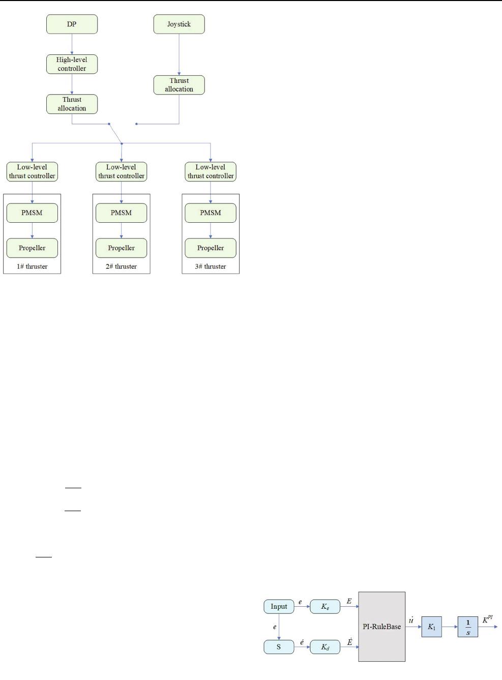
When the ship DPS is in positioning mode, the positioning
command can be given by starting DP mode or by oper-
ating the joystick. At this point, after the thrust system
receives the thrust command from the control system [29],
it uses the thrust allocation algorithm to calculate the thrust
size and direction instructions that each thruster unit needs
to achieve [30, 31]. Furthermore, each local thruster control
unit obtains the shaft rotational speed from the required
thrust map based on the static map. Finally, the thrust
coefficient is determined based on the value of the forward
speed, and the general split is divided into two cases to
obtain the corresponding values. Figure 1 shows the block
diagram of the thrust controller.
D. Wu, et al.: An Enhanced Fuzzy Control Strategy for Low-Level Thrusters…
123
2.2 Permanent Magnet Synchronous Motor
Mathematical Model
As stated in the introduction, the PMSM design is widely
used in the propulsion system for DPS as its low-level
thruster. This study also adopts the PMSM as the simula-
tion object to verify the feasibility of the fuzzy control
optimization strategy; therefore, in this part, the mathe-
matical model of the PMSM is briefly introduced.
In general, the dynamic performance of a permanent
magnet synchronous motor can be represented by the fol-
lowing formula based on the rotor d - q coordinate
system:
V
d
¼ R
S
I
d
þ
du
d
dt
p
n
x
r
u
q
V
q
¼ R
S
I
q
þ
du
q
dt
p
n
x
r
u
d
8
>
<
>
:
: ð1Þ
The mechanical equation is as follows:
T
em
¼ J
dx
r
dt
þ f
m
x
r
þ T
L
: ð2Þ
The electromagnetic torque equation is as follows:
T
em
¼ p
n
L
d
L
q
I
d
þ u
m
I
q
: ð3Þ
The meaning of each parameter is as follows: u
d
¼
L
d
I
d
þ u
m
and u
q
¼ L
q
I
q
are the total flux linkages along
the d and q-axes, respectively.
V
d
; V
q
represent d- and q-axis stator voltage, respec-
tively; I
d
; I
q
represent d and q-axis stator current,
respectively; L
d
; L
q
represent d- and q-axis stator induc-
tance, respectively; R
S
represents the stator resistance; x
r
represents the rotational frequency of the rotor in terms of
angular frequency; T
em
; T
L
are the electromagnetic torque
and load torque, respectively; u
m
is the rotor flux linkage to
the stator; J is the moment of inertia of the motor and the
load; f
m
is the motor friction coefficient; P
n
is the pole pair
number.
3 Fuzzy Control Strategy
3.1 Conventional Fuzzy Control
Professor Zadeh first proposed the concept of fuzzy set
theory and applied in a real case [32]. Fuzzy control
attempts to design controllers for systems that are struc-
turally difficult to model. Since then, fuzzy control has
become one of the most active and fruitful research areas in
the theory of fuzzy sets, it has been applied in industrial
processes, and the theory itself has many practical appli-
cations [33]. Similar to non-ambiguous 2-D and 3-D con-
trol, conventional fuzzy control also has 2-D and 3-D
control modes. Non-ambiguous two-dimensional control
methods are divided into two types, one is a proportional-
integral controller, the PI controller; the other is a pro-
portional-derivative controller, the PD controller. The PI
controller mathematical formula is as follows:
U
PI
¼ K
p
e þ K
i
Z
edt¼ K
p
Z
_
e þ T
i
eðÞdt: ð4Þ
The PD controller mathematical formula is as follows:
U
PD
¼ K
p
e þ K
d
_
e ¼ K
p
e þ T
d
_
eðÞ; ð5Þ
where e is the error,
_
e is the differential of the error,
T
i
¼ K
i
K
p
,T
d
¼ K
d
=
K
P
, if the variable e and
_
e are fuzzy
variables which form a fuzzy-PI controller and a fuzzy-
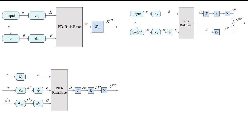
differential controller. In the continuous two-dimensional
fuzzy controller design, it is generally divided into a fuzzy-
PI controller and fuzzy-PD controller, as shown in Fig. 2
and Fig. 3, respectively:
K
e
and K
d
are the input scaling gain parameters, which
are generally determined by the actual input and the
required domain of fuzzy control. K
1
and K
2
are the output
Fig. 1 Block diagram of the thrust controller
Fig. 2 Fuzzy-PI dual-input single-output controller architecture
International Journal of Fuzzy Systems
123
scaling gain parameters, generally required by the actual
output and fuzzy output on the domain decision. The main
difference between the two lies in the selection of output
gain and fuzzy rules. The fuzzy-integral controller includes
an integral operation in the output. The output control
quantity is
_
u, which can be called the speed control
quantity and fuzzy-derivative. The output of the controller
is u; therefore, we should also pay attention to the differ-
ence between the two when designing fuzzy rules.
Fuzzy-PI controllers have inherently higher transient
response performance to higher-order processes due to
their internal integral operations, and fuzzy-PD controllers
have large steady-state errors. Considering the disadvan-
tages of these two control approaches, the fuzzy-PID
controller is chosen in this study. Since the conventional
fuzzy-PID controller is a three-input single-output fuzzy
controller, as shown in Fig. 4. For fuzzy control, the rules
increase with the number of inputs. The increment and
exponential growth are unfavorable for the optimization of
fuzzy control; thus, we have simplified the three-input
fuzzy-PID controller by sharing the PD and PI rule bases in
this study. The two-input two-output fuzzy controller
[34, 35] is simplified to achieve the controller as shown in
Fig. 4 and the simplified fuzzy controller structure is
shown in Fig. 5. This simplification can reduce the three-
input fuzzy controller to a dual-input fuzzy controller,
effectively reducing the complexity of the rules, and
facilitating subsequent optimization of the fuzzy controller.
3.2 Improved Harmony Search Algorithm
3.2.1 Harmony Search Algorithm
The harmony search (HS) algorithm is a meta-heuristic
algorithm based on music creation proposed in [20]. The
music author creates a beautiful harmonic memory based
on his own creative experience. From this, he records a
new beautiful harmony through random performance. This
cycle can result in a beautiful harmonic library. The HS
algorithm has been applied to many practical problems,
including some classical optimization problems, such as
truss design to obtain minimum structural quality, business
travel problems, and water supply network design. In
addition, the experimental data are used to reflect the
superiority of the harmony search algorithm in solving
these problems. At the same time, researchers worldwide
have investigated approaches to improve HS [21–24].
The optimization process of the harmony search algo-
rithm can be roughly divided into five parts. The steps are
as follows:
Step 1: Determine the optimization goal and algorithm
parameters.
Step 2: Initialize the harmony memory.
Step 3: Select harmony from the harmony library or
create a new solution by random playing.
Step 4: Evaluate the worst solution from the new
solution and harmony memory. If the former is better
than the latter, replace it. Otherwise, leave it as it is.
Step 5: Repeat steps 3 and 4 until the loop condition is
satisfied.
It can be seen that the process of the harmony search
algorithm is relatively simple. The new solution selects
components from the harmony memory to ensure local
search ability of the algorithm and plays randomly to
compose a new solution, thereby ensuring global search
ability of the algorithm. The entire algorithmic process of
HS has been reviewed in this study, and the setting of its
Fig. 3 Fuzzy-PD dual-input single-output controller architecture
Fig. 4 Fuzzy-PID three-input single-output controller architecture
Fig. 5 Simplified Fuzzy-PID three-input single-output controller
architecture
D. Wu, et al.: An Enhanced Fuzzy Control Strategy for Low-Level Thrusters…
123

parameters for the specific case of the HS algorithm is also
investigated. The HS algorithm is given in more detailed
procedure when considering specific problem in the fol-
lowing steps:
Step 1: Assume that our optimization problem is
specified as follows:
Min fxðÞx
i
2 X
i
; i ¼ 1; 2; ...; N
jfg
; ð6Þ
where f(x) is an objective function; x denotes the set of
each decision variable x
i
; N represents the number of
decision variables, X
i
denotes a set of possible values for
each decision variable and x
i
2½x
l
i
; x
h
i
where x
l
i
and x
h
i
upper are the lower and upper boundaries for each
decision variable, respectively.
At the same time, the parameters needed for optimiza-
tion of the harmony search algorithm need to be set,
including the harmony memory size (HMS), harmony
memory consideration probability (HMCR), pitch
adjustment probability (PAR), and the maximum num-
ber of iterations N. From these parameters, the harmony
memory consideration probability and pitch adjustment
probability are two goals that are often optimized as
parameters.
Step 2: Initialize the harmony memory. The harmony
memory can be thought of as a matrix with the harmony
memory size (HMS) as the number of rows, and the
dimension (N) of each solution is the number of
columns. Assuming that x is the solution, then the
harmony memory can use the following matrix to reflect:
HM ¼
x
1
1
x
1
2
x
1
3
x
1
D
fx
1
ðÞ
x
2
1
x
2
2
x
2
3
x
2
D
fx
2
ðÞ
x
3
1
x
3
2
x
3
3
x
3
D
fx
3
ðÞ
.
.
.
.
.
.
.
.
.
.
.
.
.
.
.
.
.
.
x
HMS
1
x
HMS
2
x
HMS
3
x
HMS
D
fx
HMS
ðÞ
2
6
6
6
6
6
6
4
3
7
7
7
7
7
7
5
:
ð7Þ
The solutions in the harmonic memory are arranged
from small to large according to its fitness value,
meaning that the first set of solutions in the harmonic
memory are the optimal solution and the last set of
solutions in the harmonic memory are the worst solution
to this harmony memory.
Step 3: Generating a new solution from the harmony
memory, select the components in the harmony memory
based on the parameters and the harmony memory
consideration probability (HMCR), or generate new
solution components randomly, as shown in the follow-
ing formula:
x
New
i
:
x
New
i
2 x
1
i
; x
2
i
; ...; x
HMS
i
t HMCR
x
r
i
t [ HMCR
; ð8Þ
where t represents a random number between 0 and 1,
if the new solution component of t B HMCR is ran-
domly selected in the harmony memory, instead it is
generated in the component definition field. After the
new solution is generated, the harmony search algorithm
also needs to fine-tune the new solution with the prob-
ability of PAR, as shown in the following formula:
Pitch Operation for X
New
i
:
Yes if rand 0; 1ðÞPAR
No if rand 0; 1ðÞ[ PAR
:
ð9Þ
Step 4: Evaluate the worst solution in harmony memory
with a new solution and update the harmony memory.
Step 5: Repeat steps 3, 4 until the loop condition is met.
3.2.2 Chaotic Random Distribution Har mony Search
Algorithm
For the HS algorithm in the case of high HMCR, the
diversity of the harmony memory only depends on random
generation. Two improvements are proposed in this study,
which distinguish it from the conventional HS algorithm.
We are not only focusing on adjusting parameters in the HS
algorithm dynamically. Instead, the harmony memory is
initialized based on chaotic operators and the values
between the solution components in the harmonic memory
are randomly assigned with a certain probability after the
harmonic memory is formed. We define the proposed
algorithm in this study as chaotic random distribution
harmony search algorithm (CRDHS).
There are many kinds of chaotic operators, including
logical mapping, tent mapping, sine iteration, and Gaussian
mapping [21]. In this paper, we use logical mapping as the
chaos operator. The value r [ (0, 1) is used as a random
parameter initialized by the harmony memory, where the
logical mapping is as follows:
X
nþ1
¼ aX
n
1 X
n
ðÞ; ð10Þ
a is set to 4 in this article [21], and X
n
is used as the
chaotic number for the iteration. Obviously when X
0
[ [0,
1] and X
0
[ {0.0, 0.25, 0.5, 0.75, 1.0}, X
n
[ [0, 1]. We use
X
n
for the initialization of each solution to be evaluated in
International Journal of Fuzzy Systems
123

our harmony memory, as shown in the following formula,
where we define X
n
as the variable r:
x
i
¼ X
i
l
þ r X
i
h
X
i
l
; i ¼ 1; 2; ; N: ð11Þ
In Eq. (11), r represents a random number between (0,
1) calculated by the chaotic operator, and x represents a
solution in the harmonic memory. X
i
l
,X
i
h
represent the
lower and upper limit of the value range of the i dimension
in each solution, respectively. In addition, in order to
overcome the deficiencies of the partial search ability of
the harmony search algorithm, we use larger HMCR and
PAR to ensure the local search ability of the harmony
search algorithm. However, in the case of larger HMCR,
the probability that the harmonic memory acquires new
solution components in each iteration is smaller, which
means that the diversity of the harmony memory is com-
pletely dependent on low probability of random generation,
which will have a negative impact on the search speed of
the algorithm. This effect often leads to a large number of
iterations to ensure completion of the search results. In this
paper, we propose a random distribution operation with the
variable Assign as the probability, by adjusting the
harmony memory in one iteration. The value of each
solution component increases its diversity, which in theory
will improve the search ability and speed of the algorithm.
The specific operation is as follows:
x
i
¼ x
i
þ r
c
x
c
x
c
¼ x
c
1 r
c
ðÞ
(
; c ¼ 1; 2; ...; N; i ¼ 1; 2; ...; N:
ð12Þ
In Eq. (12), c represents the index of the arbitrarily
chosen component in 1, 2,…, N. The index represents the
current component and the other components in the solu-
tion are randomly distributed to the data volume. If x
i
[X
i
h
occurs during distribution, the value of X
i
h
is assigned to x
i
.
Of course, this random distribution operation will only be
performed if the parameter Assign is satisfied, which can
guarantee the originality of the harmony memory and
increase its diversity in one iteration. This attribute is
conducive to the improvement of its algorithm search
capabilities. The pseudocode for this improved algorithm is
shown in Algorithm 1.
D. Wu, et al.: An Enhanced Fuzzy Control Strategy for Low-Level Thrusters…
123

The computational complexity of Algorithm 1 is ana-
lyzed as follows:
Step 1: Initialization of the harmony memory, we set the
size of the harmony memory to HMS. The dimension of
each solution is D, so the complexity of the initialization
time of the harmony memory is O(HMS
*
D).
Step 2: Calculate the fitness value of each of the
harmony memory entries and select the worst solution
among them as the solution to be compared against. The
time complexity is O(HMS).
Step 3: The new solution is selected from the harmony
memory. The operation time complexity is O(1); if the
new solution is randomly generated, the time complexity
is O(N), so the time complexity of this step is O(N).
Step 4: Randomly assign the generated solution with a
time complexity of O(N), and the time complexity of
fine-tuning is also O(N), which means the total time
complexity is O(2 N).
Step 5: Compare the generated new solution with the
worst solution in the harmony memory and decide
whether to update the harmony memory. The time
complexity is O(1).
In conclusion, the iteration number of this algorithm is
set to maxIter; thus, the complexity of this algorithm is
O(maxIter
*
(HMS ? 3
*
N ? 1)).
3.3 Fuzzy Control Strat egy Based on Chaotic
Random Distribution Harmony Search
Algorithm
For the simplified fuzzy controller input and output struc-
ture seen in Fig. 5, we employ it in the control of the low-
level thruster in which the PMSM acts as the driving motor
for the DPS. At the same time, in Fig. 5 we can see that the
selection of some parameters and determination of the
control effect of the fuzzy controller will have a certain
impact; therefore, the CRDHS algorithm is used to opti-
mize the parameters of the fuzzy controller.
In this design, our optimization method selects output
scaling gain factors K
1
and K
2
and the weights of each rule
of the two-input dual-output fuzzy model. By adjusting the
weight of each rule, the final fuzzy output can be
determined.
First, we select the fuzzy domain of the input parameters
E and E
˙
. We set the speed change to [- 600, 600]
according to the actual situation and job requirements, and
the value range of the speed change rate is [- 15,000,
15000], the fuzzy scope of the input variables, e and e
˙
are
both [- 1,1], so K
e
= 1/600, K
d
= 1/15,000 is used as the
input scaling factor. For input e and e
˙
, and the outputs
u and u
˙
, we divide them into fuzzy universes. The selected
membership function is the triangle membership function,
as shown in Figs. 6 and 7.
For fuzzy control, fuzzy rules reflect the fuzzy rela-
tionship between the input and output as a reference; it
plays an important role for the control effect, and the
PMSM is chosen as the control object in this study. In
addition, a fuzzy rules table is chosen as a fuzzy knowledge
base as shown in Table 1 [34].
After the scope of the input–output domain and the
fuzzy rules are determined, we use algorithm 1 to optimize
the weight of each rule and the output scaling factors. The
value range of the rule weight is [0, 1], and the value range
of the output scaling factors K
1
and K
2
is selected as [0,
10]. For simplification, we chose to use 10 times the ran-
dom number in the range of [0, 1] for model simulation in
the algorithm operation such that the range of values of the
parameters to be optimized is consistent, which is benefi-
cial to our optimization work.
The fuzzy control strategy based on CRDHS is specifi-
cally divided into the following steps:
Step 1: Initialize rule weights and output scaling factors.
The number of rules selected in this design is 5 9 7, or
35-rule weights, plus two-output scaling factors, K
1
and
K
2
, for a total 37 parameters (refer to 3.2.2). In other
words, the dimension N for solution x is 37, and the
Fig. 6 Input membership function curve
International Journal of Fuzzy Systems
123

range of values for each solution X is [0, 1]. It is
specifically shown by the following formula:
x
i
¼ x
1
; x
2
; ; x
j
; K
1
=
10; K
2
=
10
; ð13Þ
where x
j
, j =1,2,… 35 represents the weight of each
rule, and x
i
represents a solution in the harmony mem-
ory.
Our goal is to be able to find the appropriate combination
of parameters such that the fuzzy controller mentioned in
this article will achieve better control results. Therefore,
it is necessary to determine a standard which can eval-
uate the performance of the controller. ITAE (integration
of the time multiplied by the error absolute value), ISE
(squared error integral) and IAE (absolute error integral)
are three indicators commonly used to judge the per-
formance of a control system. Their mathematical
expressions are
ITAE ¼
Z
s
0
e
w
tðÞ
jj
tdt; ð14Þ
ISE ¼
Z
s
0
e
2
w
tðÞdt; ð15Þ
IAE ¼
Z
s
0
e
w
tðÞdt: ð16Þ
In this paper, we use ITAE as the performance index to
evaluate the fuzzy controller, and it is also the objective
function value of the chaotic random distribution har-
mony search algorithm.
Step 2: The initial harmony memory of x is sorted
according to the ITAE indicator and used as the input
harmony memory HM of the algorithm. Run Algorithm
1 to generate the ITAE value after the model has been
run completely. The objective function determines the
merits and demerits of the worst solution in comparing
the new solution and the harmonic memory.
Step 3: After algorithm 1 satisfies the loop requirement,
we record the resulting harmonic memory and assign
each component of the optimal solution x
best
to the rule
weight in the fuzzy controller and output scaling factors.
The comparisons are made among original fuzzy con-
troller, a classic PID controller, and an optimal fuzzy
controller optimized by HS and CRDHS to verify the
effectiveness of the fuzzy controller optimization strat-
egy. The specific experimental verification will be
introduced in detail in the fourth part.
Remark 1 The ITAE is chosen as the objective function. It
is very difficult to determine the type of the chosen
objective function. The deterministic annealing algorithms
such as Refs [36, 37] cannot be used in the proposed
method. Thus, the proposed CRDHS in this study is
employed to find the optimal solutions for the enhanced
fuzzy controller of the low-level thruster.
Fig. 7 Output membership function graph
Table 1 Output fuzzy rules table
u
_u
e
NB NM NS EZ PS PM PB
_
e NB B,Z B,B S,M M,B S,M B,B B,Z
NS B,Z M,S M,B S,B M,B M,S B,Z
EZ B,Z M,S B,M Z,B B,M M,S B,Z
PS B,Z S,S M,M M,B M,M S,S B,Z
PB B,Z M,M B,B B,B B,B M,M B,Z
D. Wu, et al.: An Enhanced Fuzzy Control Strategy for Low-Level Thrusters…
123

Remark 2 The designed CRDHS-based fuzzy controller
for low-level thruster receives the reference control com-
mand from high-level DPS controller [29, 38–40] and
thrust allocation module [30]. How much information
about the state of the DPS is needed depends on the high-
level controller. Moreover, it should be pointed out that the
proposed controller in this study also has some limitations,
such as offline training and speed signal feedback.
4 Simulation Results
In this section, five different controllers are employed to
control the PMSM, which are, respectively, named the PID
controller, sliding-mode controller, fuzzy-PID controller,
HS-Fuzzy PID controller and CRDHS-Fuzzy PID con-
troller. The step, rectangle and sine signals are chosen to
test the tracking speed performance. The three parameters
of the PID controller are set identically as K
p
= 0.106,
K
i
= 4.223, and K
d
= 0.0008. It should be noted that the
simulation sampling time is set to 5e-06 s, and the model
total running time is 0.1 s. The parameters used by Algo-
rithm 1 and the parameters of the PMSM are shown in
Tables 2, 3.
Case 1: Step signal-tracking performances.
Figure 8 shows the speed-tracking response curves of
different controllers under step signals, and the middle
part shows a partial enlarged view of the curves, which is
convenient for us to analyze. The results from Fig. 8
show the step-tracking performances of these five con-
trollers under the condition of no-load. The reference
speed is set to 600 n/min. It can be also seen from Fig. 8
that PID controller and SMC controller have higher
overshoot and longer response time. Fuzzy-PID and HS-
Fuzzy controllers have relatively larger overshoot and
chattering. The CRDHS-Fuzzy controller can quickly
reach the desired speed without overshooting after being
optimized by CRDHS. It has higher control accuracy and
control efficiency compared with fuzzy-PID algorithm
and HS-Fuzzy algorithm. The speed deviation results
shown in Fig. 9 demonstrated that the CRDHS-based
fuzzy controller can make the speed deviation converge
to a small value very quickly among five controllers.
Case 2: Rectangle signal-tracking performances.
Considering the ship speed regulation tests for DPS, we
also carried out relevant simulation verification for the
changing rectangular wave: the signal is changed once
every 0.02 s from the initial setting of 600 to the
transition of 300, 500 and finally remaining at 400. The
disturbance signal is chosen as a repeated discrete time
series with amplitudes [0, 0, 10, 15, 8] and each
amplitude lasts 5:0 10
6
s. The load torque T
L
is
chosen as follows:
T
L
¼
00s t\0:03s
2 sin 300tðÞ0:03s t 0:1s
: ð17Þ
From Fig. 10, we can see the continuous rectangular
wave signal when the signal is in the rising phase.
Because the fuzzy controller can reach steady state
quickly, it can reach stable speed in a short time, while
the PID and SMC controller enter steady state slowly,
which are unfavorable to the control of the system in the
case of rapid speed change. The fuzzy controller, after
being optimized by CRDHS, can reduce the steady-state
error and overshoot effectively and has better control
precision than the initial state and the fuzzy controller is
optimized only by the HS algorithm; however, it should
be pointed out that when the input is changed from a
large step to a small input, the fuzzy controller will
produce larger oscillations. Compared to the PID con-
trol, it does not produce overshooting.
Due to the load, the PID controller and the SMC con-
troller will fluctuate with the change of the load after
0.03 s. It can be seen from Fig. 10 there is a downward
Table 2 Parameters of the chaotic random distribution harmony
search algorithm
Name Symbol Value
Harmony memory size HMS 40
Harmony memory consideration probability HMCR 0.9
Pitch adjusting probability PAR 0.7
Bandwidth l 0.2
Random distribution probability Assign 0.6
Dimension of solution N 37
Maximum iteration Maxiter 1000
Range of solution X [0,1]
Parameter of logistic mapping a 4
Table 3 Parameters of the permanent magnet synchronous motor
Name (unit) Symbol Value
Rated voltage (V) U 380
Rated power (kW) P 2
Stator winding resistance (X) R
s
2.8757
Moment of inertia (kg.m
2
) J 0.8e-03
D-axis winding self-inductance (H) L
d
8.5e-03
Q-axis winding self-inductance (H) L
q
8.5e-03
Rotor field magnetic flux (Wb) W
f
0.175
Number of pole pairs P
n
4
International Journal of Fuzzy Systems
123
