
Effect of Grain Boundaries and Grain Orientation on Structure
and Properties
N. HANSEN, X. HUANG, and G. WINTHER
The evolution of deformation microstructures in metals follows a universal pattern of grain
subdivision. However, the structure in the grain boundary region may be different from that in
the grain interior, although a characteristic region cannot be identified for polycrystals with
medium to high stacking fault energy. In the grain interior, the dislocation structure is pre-
dominantly composed of almost planar boundaries (geometrically necessary boundaries) and
cell boundaries (incidental dislocation boundaries) forming a cell block structure. For grains
with grain sizes reaching down to about 4 lm deformed in tension and by rolling, a clear
correlation has been established between the characteristics of the deformation structure and the
orientation of the grain in which it evolves. A sim ilar correlation is observed for single crystals
of different orientations. Such correlations form the basis for a general analysis of active
slip systems and for modeling of the flow stress an d flow stress anisotropy of polycrystalline
samples.
DOI: 10.1007/s11661-010-0292-5
The Minerals, Metals & Mater ials Society and ASM International 2010
I. INTRODUCTION
THE microstructure evolution during plastic defor-
mation of polycrystals may differ from that of single
crystals due to grain interaction. A first attempt to relat e
the behavior of single crystals and polycrystals was
made by Sachs,
[1]
who suggested that individual grains
in polycrystals deform like free single crystals. However,
as strain continuity must be maintained across the grain
boundaries, it was suggested by Taylor
[2]
that all the
grains in a polycrystal undergo the same homogeneous
strain as the bulk mate rial. Such a homogeneous strain
will, in general, require slip on at least five slip systems.
[3]
The presence of grain boundaries was not taken into
account in the Taylor model. Boundaries may, however,
be effective barriers to slip so that local stresses
potentially build up in the grain boundary region. These
may be relaxed by secondary slip. As a result, the
microstructure evolving in the grain boundary region
may differ from that of the grain interior. The structural
evolution in these regions will be presented in the
following as an overview based on structural subdivi sion
by deformation-induced dislocation boundaries. In the
next section, correlations will be presented on the grain
scale between the characteristics of the deformation
microstructure and the crystallographic orientation of
the grain in which it forms. This leads to a comparison
of polycrystal and single-crystal beh avior followed by a
general analysis of active slip systems. In a final section,
the mechanical behavior of single crystals and polycrys-
tals will be discussed.
II. DEFORMATION
MICROSTRUCTURE—GENERAL
The characterization and analysis of deformation
microstructures will in the present paper be limited to
fcc metals with medium to high stacking fault energy
ranging from 45 mJ/m
2
(Cu) to 166 mJ/m
2
(Al).
[4]
Only
cold deformation will be discussed and at strain rates
where diffusional processes are considered to be negli-
gible. As to deformation, monotonic deformation pro-
cesses like tension and rolling will be included. By these
processes, the equivalent strain (e
vM
) has been varied
from low to medium levels (about 0.05 to 0.5, where
single glide is precluded). As a general guideline for the
structure analysis, it is assumed that the dislocations are
stored in low-energy configurations almos t free of long-
range stresses.
[5–7]
A. Grain Boundary Region
The effect of grain bounda ries during plastic defor-
mation was introduced by Kockendo
¨
rfer
[8]
who sug-
gested that the interior of a grain in a polycrystal may
deform like an isolated single crystal and the misfit
where the grains meet might be accommodated elasti-
cally or plastically. Strain accommodation in the grain
boundary region was also considered by Hauser and
Chalmers,
[9]
who suggested that it will lead to multislip
in the vicinity of the grain boundary wi thin a distance of
the order of the spacing between the slip bands, i.e.,a
few micrometers. They also suggested that the existence
of such a multislip layer (zone of misfit) of a certain
thickness might explain the grain size effect on the
N. HANSEN, X. HUANG, and G. WINTHER, Senior Scientists,
are with the Danish-Chinese Center for Nanometals, Materials
Research Division, Risø National Laboratory for Sustainable Energy,
Technical University of Denmark, DK-4000 Roskilde, Denmark.
Manuscript submitted December 23, 2009.
Article published online July 13, 2010
METALLURGICAL AND MATERIALS TRANSACTIONS A VOLUME 42A, MARCH 2011—613
strength of polycrystals.
[9]
The formation and effect of
such a ‘‘rim’’ being harder than the grain interior has
also been considered in various mo dels, e.g., Reference
10. An alternative approach suggested by Ashby
[11]
was
to consider the strain accommodation in terms of
dislocations, and separating the deformation of individ-
ual grains into a homogeneous deformation of the grain
interior and a local nonuniform deformation in the
grain boundary region. During homogeneous deforma-
tion, statistically stored dislocations with a density q
s
accumulate as in an equivalent single crystal, where q
s
is
proportional to the plastic strain and increases as the
slip length decreases. To correct for voids or overlaps in
the grain boundary region, geometrically necessary
dislocations of density q
g
were introduced where q
g
is
proportional to the plastic strain and inversely propor-
tional to the grain size. The total dislocation density
increases with the strain, however faster for q
s
than for
q
g
, as the slip distance decreas es rapidly with increasing
strain.
Grain interaction effects may manifest themselves by
local changes in microstructure and crystallography in
the grain boundary region. Such changes have been
observed by scanning electron microscopy (SEM) of
surface relief structures and by transmission electron
microscopy (TEM) of microstructures at or near grain
boundaries.
[12]
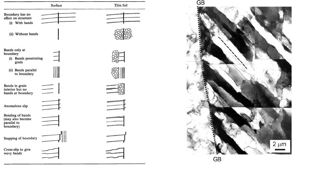
Results in Figure 1 show good agreement
between the SEM and TEM observations, which indi-
cates that the structure in the grain boundary region
may differ from that in the grain interior but also that a
grain boundary region (rim) with typical characteristics
has not formed. However, the preceding observations
also show that the interior structure may extend all the
way to the boundary. Similar observations in tensile-
deformed Al and Cu are shown in Figures 2 and 3,
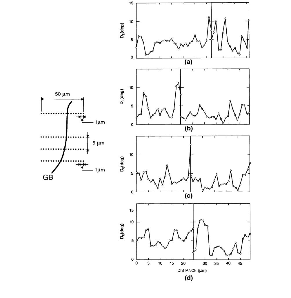
respectively. Grain interaction has also been studied by
EBSD parallel and perpendicular to grain boundaries
where interaction is identified as perturbations that
reflect local changes in crystallography.
[13]
For speci-
mens deformed to 5 pct reduction in thickness by cold
rolling, significant perturbations are observed at triple
junctions but not in the grain boundary region. How-
ever, when the reduction is increased to 30 pct, pertur-
bations are observed at many grain boundaries
(Figure 4). These perturbations may extend some
micrometers into the grain from the boundary to be
compared with a grain size of about 300 lm. In order to
quantify such regions and their dependence on grain size
and strain, more extensive studies are needed, which are
now within reach with advanced EBSD techniques.
The studies of grain inter action have been coupled
with an analysis of the structural evolution in grains in
high-purity copper deformed in tension to a strain of
25 pct.
[14]
A relatively coarse grain size has been chosen,
which allows grain break-up and lattice rotations to be
followed by EBSD analysis of individual grains as a
function of strain. As shown in Figure 5, a few small
domains of special orientations provide evidence of
grain interaction. However, the crystal rotation for the
large domains covering most of the grains is consistent
with the rotation direction predicted by the Taylor
model in some, but not all, cases.
[14]
Fig. 1—Classification of structures at grain boundaries in cold
deformed aluminum. Surface structures seen by SEM or optical
microscopy in the left column correspond to structures seen in TEM
in the right column.
[12]
Fig. 2—TEM image showing that a uniform dislocation structure
extends from the grain interior all the way to the grain boundary in
a tensile-deformed Al.
[28]
The grain boundary is marked by a dotted
line. The dashed line on the micrograph indicates the trace of the
primary slip plane.
614—VOLUME 42A, MARCH 2011 METALLURGICAL AND MATERIALS TRANSACTIONS A
B. Grain Interior
The microstructural evolution in the grain interior can
be characterized as structural subdivision with easy
mobility of disl ocations that assemble into dislocation
boundaries. On the coarse scale, the structure subdivides
by the formation of domains (e.g., Figure 5) and
deformation bands; on a fine scale, almost planar
boundaries and cell boundaries forming cell blocks are
typical features. However, on an intermediate scale,
longer range orientation gradients may develop in the
cell block structure, for example, as shown by orienta-
tion imaging microscopy in pure aluminum deformed by
cold rolling.
[15]
In the following, the structural subdivi-
sion will be described based on the cell block as the basic
structural feature. Such a cell block contains a group of
cells in which the same set of slip systems operate, which
may fall short of that required for homogeneous
(Taylor) deformation, leading to the suggestion that
groups of neighboring cell blocks can fulfill the Taylor
criterion collectively.
[16]
The observed co-existence of disl ocation cells and
extended dislocation boundaries has led to a classifica-
tion of dislocation boundaries into the following:
[17]
(1) incidental dislocation boundaries (IDBs), which
are assumed to form by statistical trapping of glide
dislocations;
(2) geometrically necessary boundaries (GNBs), which
are assumed to form due to the different character
of the slip-induced glide dislocations in neighbor-
ing volumes.
Both types are typically rotation dislocation bound-
aries, which can be characterized by an axis/angle pair
and a boundary normal. This classification into IDBs
and GNBs adds to the classical distinction between
dislocations as statistically stored (redundant) and
geometrically necessary (nonredundant) dislocations
[11]
(Section A). The statistically stored dislocations are
assumed to be present in the form of tangles, dipoles,
and multipoles, which will not give rise to a significant
lattice rotation; i.e., their net Burgers vector is practi-
cally zero. In contrast, the geometrically necessary
dislocations are assumed to assemble in configurations
characterized by a lattice rotation and a net Burgers
vector. The storage of these dislocations can be random
or the dislocations can be assembled in boundaries in
which the lattice rotation is reflected in the misorienta-
tion angle across the boundary. A distinction between
statistically stored and geometrically necessary disloca-
tions is not possible through a microscopic examination
of the microstructure. However, a separation has been
attempted by X-r ay microdiffraction of deformed sam-
ples where streaking of Laue spots is interpreted as due
to an elastic strain gradient or to a distribution of
geometrically necessary dislocations. In contrast, a split
of the Laue pattern indicates angular misorientati ons
between neighboring volumes, i.e., the presence of
GNBs.
[18]
The classification of dislocation boundaries has been
the basis for the analysis of experimental observations
and their physical interpretation. In general, this anal-
ysis has covered a variety of bounda ry parameters, most
notably the spacing between and the misorientation
angle across dislocation boundaries. Sample scale aver-
age values have been obtained as well as distributions of
structural parameters. By analyzing such distributions,
it has been found that both spacing and misorientation
angle can be described by a single universal function
when each distribution is scaled by its mean angle or
spacing.
[19]
Such a scaling hypothesis ap plies to both
GNBs and IDBs, when they are analyzed separately but
not when they are grouped together. Scaling of the
spacing between GNBs has also shown a similarity in
the behavior of polycrystals and single crystals deformed
in rolling and compression.
[20]
A part of the microstructural analysis has also been to
apply the principle of similitude
[5]
expressing a fixed
relationship between structure parameters, e.g., between
the boundary spacing ( D) and the spacing (h) between
the dislocations in a boundary. Taking h inversely
proportional to the misorientation angle (h), similitude
can be expressed by the equation Dh/b = C, where b is
the magnitude of the Burgers vector and C is a constant.
For cell structures in aluminum deformed in tension and
by rolling, C varies, on average, in the range 50 to 80 rad
with no significant effect of stra in.
[6]
However, the
principle of similitude does not apply to the whole
structure as cell blocks and cells evolve differently with
increasing strain
[6]
(see Section III–D).
III. GRAIN ORIENTATION DEPENDENCE
A systematic study has been carried out on the
relationship between the grain orientation and the
dislocation structure for Al, Cu, and Ni of different
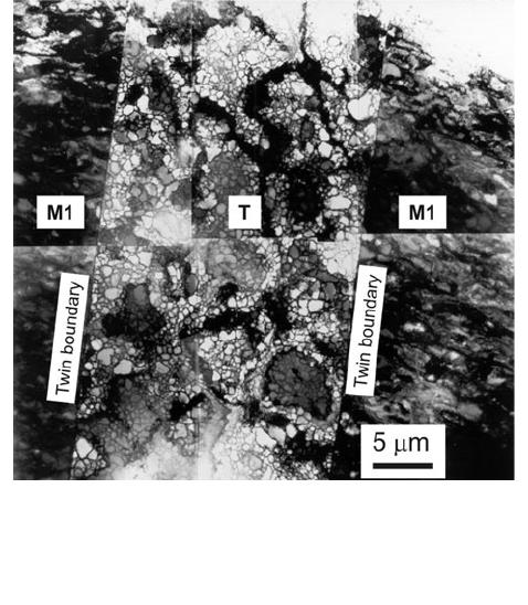
Fig. 3—TEM image taken from the cross section of a tensile-
deformed Cu. A uniform cell structure is formed in the twin (T),
which is in contrast to the structure in the matrix parts (M1). There
is no clear effect of twin boundaries on the structural evolution in
the twin and matrix parts.
METALLURGICAL AND MATERIALS TRANSACTIONS A VOLUME 42A, MARCH 2011—615
purities and grain sizes,
[21–29]
mainly based on TEM
characterization where great care has been taken in the
experimental design and structural characterization.
(1) The materials have been deformed in tension and by
cold rolling to study the effect of deformation mode.
(2) TEM observations have been performed in differ-
ent sample sections to obtain a precise description
of the three-dimensional (3-D) arrangement of the
dislocation structure.
(3) The crystallographic planes of GNBs have been
determined for selected grains, showing that the
GNB planes depend on the grain orientation.
The precise characterization of the 3-D morphology
and GNB planes establishes a universal pattern of
structural evolution, which is characterized by forma-
tion of three structure types leading to the conclusion
that among the materials parameters (grain orient ation,
grain size, grain boundary, and impurity) the grain
orientation is the most important in controlling the
structural evolution. This effect is described in this
section by taking a tensile-stra ined Cu polycrystal and a
cold-rolled Cu polycrystal as examples. Analysis of the
underlying processes (slip systems) governing the
development of different structure types and detailed
Fig. 4—Examples of orientation scans perpendicular to a grain boundary, sampled according to the schedule shown in the figure in 30 pct
deformed, coarse-grained sample.
[13]
616—VOLUME 42A, MARCH 2011 METALLURGICAL AND MATERIALS TRANSACTIONS A

comparison with single crystals are presented in Sections
IV and V.
A. Grain Orientation and Structure Types in Tension
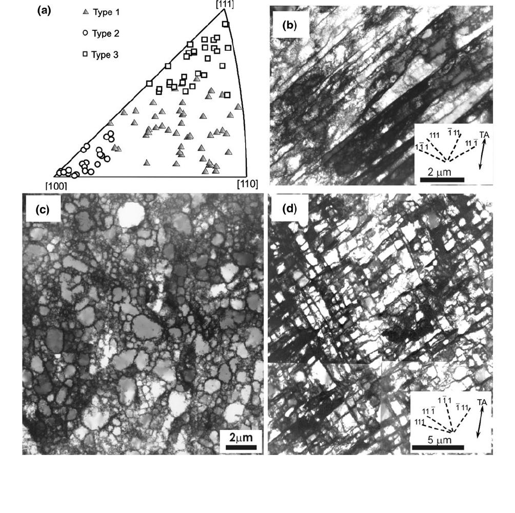
Figure 6 shows the tensile orientations of 120 grains
(Figure 6(a)) analyzed in a tensile-deformed 99.99 pct
pure Cu with a grain size of 90 lm and the three
structure types (Figures 6(b) through (d)). The charac-
teristics and dependence on grain orientation for each
structural type are summarized in the following.
[26,28]
The type 1 structure (Figure 6(b)) is a cell block
structure with cell block boundaries (GNBs) aligned
approximately with the slip planes (within 10 deg). The
grains forming the type 1 structure have their tensile
axes in the middle pa rt of the triangle (Figure 6(a)). The
GNBs are straight and parallel, and thus have a well-
defined macroscopic orientation with respect to the
tensile axis (TA). The slip plane to which the GNBs are
related is in most cases the primary slip plane defined by
the largest Schmid factor value and, in some cases, the
conjugate slip plane for grains near the [100]-[111]
boundary (where the Schmid factor of the conjugate slip
system is similar to that of the primary one).
The type 2 structure (Figure 6(c)) is a cell structure
without GNBs. The grains showing this type of struc-
ture have their tensile axes in a small area near the [100]
corner (Figure 6(a)). The cell boundaries are randomly
oriented in the cross section, as seen in Figure 6(c), and
are extended along the TA in the longitudinal section
(for examples of micrographs for tensile-deformed Cu of
different grain sizes, see References 22 and 26). There-
fore, the type 2 structure in Cu is a 3-D cylindrical cell
structure.
The type 3 structure (Figure 6(d)) is also a cell block
structure similar to type 1, but the GNBs deviate
substantially from the slip planes (>10 deg). The grains
developing the type 3 struc ture have tensile axes in the
upper part of the triangle toward the [111] corner. Each
GNB is made up of a number of long or short segments.
The majority of the segments are oriented in similar
directions with respect to the TA, but segments that
have different macroscopic orientation and form angles
of up to about 20 deg with the dominating segments also
exist. These features give rise to a fairly clear macro-
scopic inclination of the GNB s over a long distance but
a somewhat curved appearance on a local scale.
Minor morphological differences were found in the
type 2 structure between Cu, Ni, and Al. Recent
observations of tensile-deformed Ni
[29]
showed a sim ilar
3-D cylindrical cell structure as in Cu. However, the type
2 structure in tensile-deformed high-purity Al is char-
acterized by a 3-D equiaxed cell structure,
[28]
which
implies a possible effect of stacking fault energy on the
cell structure morphology. Interestingly a co-existence
of a 3-D cylindrical cell structure and a 3-D equiaxed
cell structure was observed in commercial purity Al,
indicating an effect of impurities.
[28]
B. Grain Orientation and Structure Types in Cold Rolling
Similar to the observation in tensile-deformed Al, Cu,
and Ni, three structure types and their grain orientation
dependence have also been identified in cold-rolled
samples. Figure 7 shows the results for a cold-rolled
99.99 pct pure Cu with a grain size of 90 lm. Clusters of
orientations showing a type 1 structure are seen within
15 to 20 deg of the ideal Goss, Brass, and rotated Cube
orientations. Grains within 15 deg of the Cube orienta-
tion develop a type 2 structure, which shows elongated
cell boundaries parallel to the rolling direction (RD)
in the longitudinal section. Clusters of orientations
Fig. 5—Subdivision of a coarse grain in copper deformed in tension at e
vM
= 0.08. The gray shaded regions are coarse domains, and the hashed
regions are grain interaction domains.
[14]
The white domain represents an annealing twin.
METALLURGICAL AND MATERIALS TRANSACTIONS A VOLUME 42A, MARCH 2011—617
showing a type 3 structure are seen >15 deg from the
Cube and along the b fiber from S to Copper. For the
type 2 structure formed in the Cube grains, when
observing the transverse section, a circular or equiaxed
cell structure was always found. The combined obser-
vations from the longitudinal and transverse sections
reveal a cylind rical morphology of the type 2 structure
in the Cube grains, basically identical to that found in
grains near the [100] corner in the tensile-strained Cu.
Recent observations
[29]
showed that the type 2 struc-
ture in cold-rolled Ni also exhibits a cylindrical mor-
phology, as in Cu described previously. However, the
Cube grains in cold-rolled Al developed a 3-D eq uiaxed
cell structure,
[29]
as found in tensile-deformed high-
purity Al.
[28]
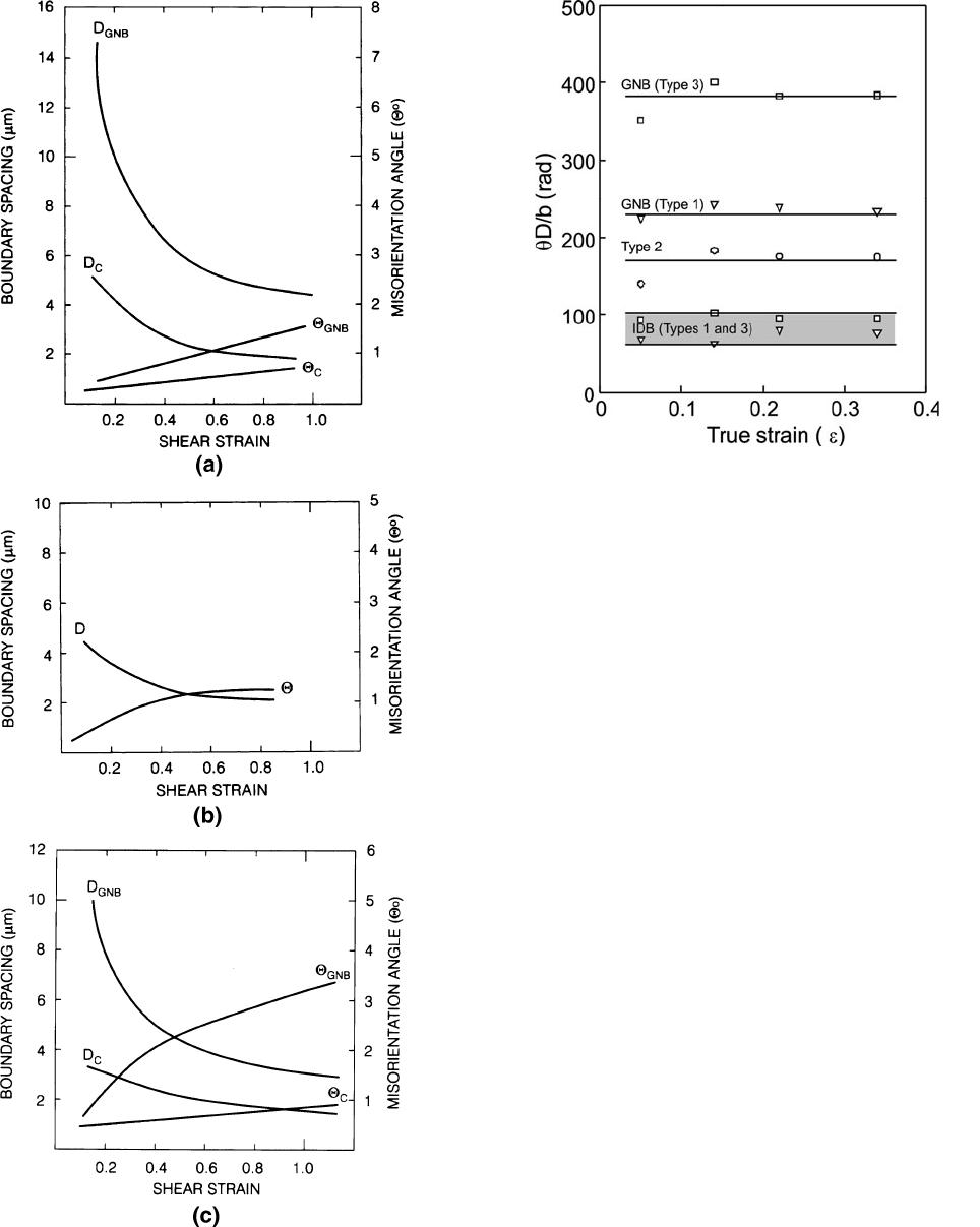
C. Spacing and Misorientation Angles
The grain orientation does not only affect the struc-
tural morphology and the crystallographic GNB align-
ment but also the structural parameters.
[30]
This is
illustrated in Figure 8 showing the evolution of bound-
ary spacings and misorientation angles in grains repre-
senting type 1, 2, and 3 structures. Note that the
evolution of the type 2 parameters differs from those of
type 1 and 3, and that the evolution of spacing and angle
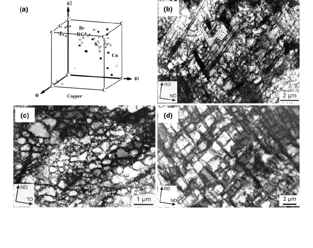
Fig. 6—Grain-orientation-dependent structure types in a tensile-strained 99.99 pct Cu (grain size = 90 lm). (a) TA orientations of 120 grains,
which have been examined.
[28]
Three symbols, filled triangle, open circle, and open square, are used to separate the grains developing type 1,
type 2, and type 3 structures, respectively. (b) through (d) TEM images to illustrate the characteristic features of (b) type 1, (c) type 2, and (d)
type 3 structures. Among these images, the ones shown in (b) and (d) were taken from the section // TA, and that shown in (c) was taken from
the section ^ TA.
618—VOLUME 42A, MARCH 2011 METALLURGICAL AND MATERIALS TRANSACTIONS A
for both GNBs and IDBs is more rapid in type 3
structures than in type 1 structures.
D. Scaling and Similitude
The misorientation data were analyzed according to
the scaling hypothesis,
[19]
and it was found that GNBs
and IDBs, when treated separately, agree well with
earlier observations. However, the angular variation in
the type 2 structures is not in accord, pointing to
different mechanisms of formation and evolution.
The similitude relating the boundary misorientation
angle and spacing (as discus sed in Section II–B) was also
analyzed for tensile-deformed high-purity Al. It was
found that the principle of similitude does not apply at
the sample scale average, as the cell block boundaries
and the cell boundaries evolved differently with increas-
ing strain. These findings have been confirmed by
analysing the three structure types separately. The C
values derived from the data are given in Figure 9,
which shows that C is fairly independent of the strain,
but significantly different for the different structure
types. Note, however, that all the IDBs are in the range
from 60 to 100 rad in good agreement with the earlier
measurements.
[6]
E. Effect of Grain Size
The reduction in spacing between deformation-
induced boundaries from fairly high values at low strain
(and stress) to about 1 to 4 lm at an equivalent strain of
about 1 (Figure 8) raises the question of a lower limit in
grain size for the universal evolution of type 1 through 3
deformation microstructures. For example, will such
structures form when the grain size is very small? To
address this problem, a technique is required for
producing fine-grained polycrystalline samples. This is
possible by recrystallization after deformation to very
high strain, for example, by torsion,
[27,31,32]
and it has
been possible to obtain a grain size in Cu of about 4 lm
after applying a true strain of about 8 followed by
annealing at 523 K (250 C). This sample has been
deformed in tension to true strains of 0.15 and 0.20 and
characterized by TEM.
[27]
By examining the structure in
21 grains, it has been concluded that type 1 through 3
structures evolve and that their orientation dependence
Fig. 7—Grain-orientation-dependent structure types in a cold-rolled 99.99 pct Cu (grain size = 90 lm). (a) 3-D Euler space showing the orienta-
tion of 56 grains examined.
[28]
Filled triangle, circle, and square show type 1, type 2, and type 3 structures, respectively. The star symbol shows
grains with two sets of GNBs, one of type 1 and the other of type 3. Several ideal orientations are also indicated. G: Goss (110)[001], Br: Brass
011ðÞ2
11
; RC: 45 deg ND rotated Cube (001)[110], S: (213)
3
64
; Cu: Copper (112)
1
11
; and C: Cube (001) (100). (b) through (d) TEM ima-
ges to illustrate the characteristic features of (b) type 1, (c) type 2, and (d) type 3 structures. Among these images, the ones shown in (b) and (d)
were taken from the TD section and that shown in (c) was taken from the RD section.
METALLURGICAL AND MATERIALS TRANSACTIONS A VOLUME 42A, MARCH 2011—619
is identical to that observed in Cu samples having larger
grain sizes (50 to 190 lm). It has also been found
[27]
that
the deformation microstructure is fairly uniform across
the area of the small grains and that a specific grain
boundary region with a structure different from that of
the grain interior has not developed.
IV. SLIP SYSTEM DEPENDENCE
The orientation dependence of the main dislocation
structure types can be explained in terms of an under-
lying dependence on the active slip systems, which
suggests that combinations of slip systems leading to
structure types 1, 2, and 3 can be identified. This further
implies that if similar slip system combinations are
activated under different circumstances, e.g., different
combinations of crystal/grain orientation and deforma-
tion mode, the structure type should be the same.
Analysis of the active slip syst ems in crystals/grains with
the different types of structures has been conducted for
tension and rolling,
[33]
focusing on cases where the active
slip systems can be predicted fairly unambiguously by
the Taylor model and Schmid factors. The result is the
identification of five classes of slip system combinations,
which lead to specific structure types. Table I summa-
rizes the relations between slip classes and structure
types, and these are described in more detail in Section A.
A. Slip Classes and Structure Types
For the type 1 structure, it is found that the GNBs
always align with a highly active slip plane.
[34]
When
conducting an even more detailed study of the type 1
Fig. 9—The principle of similitude for the GNBs and IDBs in a ten-
sile-deformed 99.99 pct Al.
[30]
Fig. 8—Dislocation boundary spacing (D) and misorientation angle
(h) as a function of strain for the three different structure types
developed in a tensile-deformed 99.99 pct Al.
[30]
The subscript C
refers to IDBs.
620—VOLUME 42A, MARCH 2011 METALLURGICAL AND MATERIALS TRANSACTIONS A

structure, it is found that it falls into two subcategories,
both having GNBs aligned with {111} planes but with
different systematic small deviations from the ideal slip
plane. These deviations are by rotations of a few degrees
(up to 10 deg) around a specific crystallographic axis,
which may be either a 112
hi
or a 110
hi
axis.
[27]
The
existence of these two subcategories implies an under-
lying difference in slip systems, which is the basis for
definition of two different slip classes. Detailed analysis
of a number of cases concludes that the difference lies in
the number of active slip systems on the slip plane so
that deviations around 112
hi
axes result from one active
system while the 110
hi
axes originate from activation of
two systems in the same slip plane (in the following,
referred to as coplanar systems).
[33]
For the type 2 structure, the common feature of the
slip systems is the activation of codirectional pairs of slip
systems, i.e., two systems on two different slip planes but
with the same slip direction. When comparing different
cases, it is concluded that at least two sets of codirec-
tional slip systems (i.e., a total of four systems) must be
activated to produce type 2. The sign of the dislocations
gliding on the slip systems also plays a role (Reference
33 provides more details).
For the type 3 structure, the number of subcategories
is the highest and the difference between subcategories is
much larger than for type 1. Table I lists the different
GNB planes observed and divides them into two
subcategories, each of which is associated with activa-
tion of a slip class. Please note that in all cases the GNB
planes lie far from a slip plane, in agreement with the
definition of the type 3 structure. The two slip classes
consist of the following combinations of slip systems.
(1) One set of codirectional slip systems. The GNBs
align with a plane containing the common slip
direction and bisecting the angle between the two
slip planes. The GNB lies closer to the more active
slip plane and the signs of the slip systems control
whether the GNB bisects the acute or obtuse angle
between the slip planes.
(2) So-called dependent coplanar and codirectional
slip, which is a combination of three systems on
two slip planes where one system is codirectional
and coplanar to the other two, respectively. Sev-
eral such slip system combinations may be acti-
vated in the same grain, possibly sharing some of
the slip systems, which gives rise to a number of
characteristic GNB planes. For more details, see
Reference 33.
The relations between slip classes and structure types
are of universal nature in the sense that they are not
restricted to any deformation mode or grain orientation.
The identification of these relations establishes a new
framework for the analysis and interpretation of struc-
tures, as exemplified in Sections IV–B, V,andVI–B.
B. Applica tion of Slip Classes
By means of the slip class concept, some of the
fluctuations observed between grains of similar orienta-
tion or within a grain can be better understood. The
occurrence of both type 1 and 3 boundaries a long the b
fiber of the rolling texture
[28]
is, for example, due to
activation of both a coplanar set of slip systems and a
codirectional set, leading to type 1 and 3 boundaries,
respectively. It is often observed that either the type 1 or
3 boundary is more clearly developed. In most cases,
however, the second set can also be detected. These
variations are attributed to local variations in the
relative activities of the slip systems, possibly caused
by minor strain variations or ambiguities. Analogously,
one or two sets of type 1 GNBs are found in grains of
Goss or Brass
[28]
orientation, depending on the activities
on the two slip planes with which the GNBs align. It is,
however, emphasized that these variations have their
origin in fluctuations in the relative activities of a fixed
set of slip systems, which can be pred icted based on the
grain orientation, rather than activation of new syst ems,
which can only be predicted based on detailed interac-
tions with neighboring grains.
Of course, the relations can also be used to predict the
structure based on the slip systems. For example, the
relations have been applie d to predict the dominant
alignment of the structure after torsion for the major
stable texture components, giving good agreement with
experimental observations.
[33]
This further served as a
demonstration of the uni versality by being a prediction
for a deformation mode other than tension and rolling.
The ability to predict the structure type is also vital for the
modeling of mechanical properties, as demonstrated in
Section VI.
V. SINGLE VS POLYCRYSTALS
The classification into three main types of structures,
of which types 1 and 3 can be subdivided further
according to the exact plane of the GNBs, has been
presented and analyzed above for grains in polycrystals.
Table I. Relations between Slip Classes and Dislocation Structures (Reference 33 Provides More Details)
Slip Class Crystallographic GNB Plane Structure Type
Single slip {111} type 1
Coplanar slip {111} type 1
Two sets of codirectional slip no GNBs, only cells type 2
One set of codirectional slip
symmetric
{101} or {010}* type 3
Dependent coplanar and directional slip {315}, {441}, or {115} type 3
*Depending on the signs of the Schmid factors. Asymmetric codirectional slip brings the GNB plane closer to the more active slip plane.
METALLURGICAL AND MATERIALS TRANSACTIONS A VOLUME 42A, MARCH 2011—621
The classification applies equally well to single crystals,
and furthermore, the structure type follows the crystal/
grain orientation in almost the same way.
A. Type 1
A comparison with the orientation dependence of
type 1 structures between single crystals and grains in
polycrystals reveals a strong similarity.
(1) In tension single crystals in the middle of the stereo-
graphic triangle exhibit type 1 structures (e.g.,
References 35 and 36). Type 1 boundaries are also
found in crystals on the 100
hi
- 111
hi
symmetry line
of the triangle when these lie more than 15 to 20 deg
away from either 111
hi
or 100
hi
:
[37]
Similarly, single
crystals on the 110
hi
- 111
hi
symmetry line exhibit
type 1 structures if they are more than about 15 deg
away from 111
hi
:
[37]
This orientation range corre-
sponds well with the occurrence of type 1 structures
in polycrystals in all orientations somewhat away
from 100
hi
and 111
hi
(Figure 1(a)).
(2) In rolling, both single crystals and grains with sta-
ble rolling texture orientations develop type 1
structures: on the a-fiber, two sets of GNBs
aligned with {111} are typically observed (single
crystals
[38–41]
and polycrystals
[23,28]
), while only one
set aligned with {111} is found on the b fiber (sin-
gle crystals
[42]
and polycrystals
[28]
), sometimes
coexisting with type 3 boundaries.
Looking at the subcategories of type 1 boundaries,
i.e., the character of the small deviations from the exact
{111} plane, the similarities also hold. In tension, type 1
boundaries deviate from the {111} plane by being
rotated slightly away from this around 112
hi
axes.
[25,28]
The exception is single crystals lying on the 110
hi
- 111
hi
symmetry line, where the corresponding axis is of the
110
hi
type.
[37]
In rolling, these small deviations from the
{111} planes are less well characterized for both single
crystals and grains, but rotation around 110
hi
axes has
been reported.
[28]
B. Type 2
In polycrystals, grains fairly close to the exact 100
hi
and Cube orientations, in tension
[28]
and rolling,
[28,29]
respectively, exhibit type 2 structures (Figures 1(c) and
7(c)). This is in good agreement with the findings in
single crystals of 100
hi
[42]
and Cube orientations ,
[44]
respectively.
C. Type 3
In tension, type 3 structures are found in both single
crystals
[43]
and grains
[28]
of near 111
hi
orientation. The
orientation range with type 3 structures in polycrystals
includes all orientations within 15 to 20 deg of 111
hi
:
Type 3 structures in single crystals have also be en
reported for crystals lying on the symmetry lines
bounding the stereographic triangle within 15 to
20 deg of 111
hi
:
[37]
To the authors’ knowledge, no data
are available on the structure type for crystals lying close
to 111
hi
but inside the triangle. Considering the subcat-
egories of type 3 structures, some differences are
reported between single crystals and polycrystals. In
single crystals, GNBs roughly aligned with {135} and
{441} planes are observed on the 100
hi
- 111
hi
and 110
hi
-
111
hi
lines, respect ively.
[37]
By contrast, the planes
reported in polycrystals are {135} and {115}.
[28]
In rolling, type 3 structures are found in grains some
distance away from the Cube orientation (right outside
the orientation range with type 2 structures).
[28,29]
This is
in agreement with the structures observed in parts of a
Cube-oriented single crystal that had rotated somewhat
away from the initial Cube orientation.
[44]
In both single
crystals and grains of near Cube orientation, the type 3
boundaries aligned with {101} planes.
[28]
Both single-
crystal
[42]
and polycrystal orientations
[28,45]
on the b
fiber of the rolling texture develop type 3 structures
(together with GNBs aligned with slip planes). For the
Copper orientation, GNBs align with {100} in both
single crystals and polycrystals.
[28,42]
D. Similarity between Single and Polycrystals
Based on the preceding analysis, it is concluded that
structures of type 1 through 3 are found in both single
crystals and polycrystals and that single crystals and
grains of similar orientations in general develop the same
structure type. This is evidence of activation of similar slip
systems. It is particularly interesting that type 1 structures
with a 112
hi
deviation axis are found in both single
crystals and grains in the middle of the triangle. It is
generally accepted that these single crystals deform in
single glide, while the Taylor model often applie d to
polycrystals predicts up to eight active systems. The
structure observations suggest that also the grains have
one dominant slip system, which may, however, be
accompanied by minor activity on other systems. It
should be noted that the lattice rotations of individual
grains of these orientations have also been observed to be
in good agreement with one dominant system.
[46,47]
However, some minor discrepancies are observed
when considering the exact GNB plane in tension
around the 111
hi
orientation. Furthermore, the expec-
tation is that single crystals fairly close to 111
hi
and
100
hi
inside the triangle will also deform in single glide,
while grains in polycrystals of these orientations develop
type 3 and 2 structures, respectively. The origin of this
discrepancy is likely to be activation of a larger number
of slip systems in grains compared to single crystals due
to the restrictions imposed by the neighboring grains
combined with the availability of a number of slip
systems with almost equal Schmid factors in these
orientation ranges. Similar discrepancies between single
crystals and polycrystals ha ve not been reported for
rolling, probably because of the inherent tendency of
rolling to induce multislip in all crystals/grains.
VI. MECHANICAL PROPERTIES
The mechanical properties of deformed polycrystals
will be affected on the sample scale by a different
622—VOLUME 42A, MARCH 2011 METALLURGICAL AND MATERIALS TRANSACTIONS A
