The Effect of Microstructure and Environment
on Fatigue Crack Closure of 7475 Aluminum Alloy
R.D. CARTER, E.W. LEE, E.A. STARKE, Jr., and C.J. BEEVERS
The effects of slip character and grain size on the intrinsic material and extrinsic closure contributions
to fatigue crack growth resistance have been studied for a 7475 aluminum alloy. The alloy was tested
in the underaged and overaged conditions with grain sizes of 18/xm and 80/xm. The fracture surface
exhibited increased irregularity and planar facet formation with increased grain size, underaging, and
tests in vacuum. These changes were accompanied by an increased resistance to fatigue crack growth.
In air the 18/xm grain size overaged material exhibited relatively poor resistance to fatigue crack
growth compared with other microstructural variants, and this was associated with a lower stress
intensity for closure. All materials exhibited a marked improvement in fatigue crack growth resistance
when tested in vacuum, with the most significant difference being -1000• at a AK of 10 MPa m v2
for the 80/xm grain size underaged alloy. This improvement could not be accounted for by either
an increase in closure or increased crack deflection and is most likely due to increased slip reversi-
bility in the vacuum environment. The intrinsic resistance of the alloy to fatigue crack growth
was microstructurally dependent in vacuum, with large grains and planar slip providing the better
fatigue performance.
I. INTRODUCTION
TRADITIONAL design of cyclically loaded components
utilizes the fatigue endurance limit: a parameter experi-
'mentally determined using defect-free samples, l Lately,
fracture mechanics concepts have been used in conjunction
with nondestructive measurements of defects to establish the
maximum cyclic stress below which a detectable crack will
not grow. 2'3 The resulting design parameter used for the
preexisting defect tolerant approach is the threshold stress
intensity range, AK~. Recent studies have shown that the
magnitude of this experimentally determined parameter can
be greatly influenced by closure effects. Elber 4 pointed out
the existence of crack closure in 1970 when he observed that
a crack in a fatigue specimen was closed during a portion
of the loading cycle, even when the minimum load was
tensile. Since crack closure always gives a positive effect,
i.e.,
it reduces fatigue crack growth rates, there is con-
siderable interest in identifying the mechanisms associated
with closure.
Fatigue crack closure was considered by early researchers
to be only a plane stress phenomenon 5 caused by the re-
straint of elastic material surrounding permanent plastic ten-
sile deformation left in the wake of the propagating crack, 4
and was termed "plasticity-induced crack closure. ''6 Later,
crack closure was found to be significant in thick specimens
under plane strain conditions, and attributed to crack
branching and Mode II displacements. 7 Closure resulting
from mode II displacements requires a rough or uneven
fracture surface and is termed "roughness-induced crack
closure. ''6 An oxidizing environment may also influence
closure behavior, and Ritchie and Suresh 8 suggest that
R. D. CARTER is an Engineer, United States Army Corps of Engineers,
P.O. Box 61, Tulsa, OK 74121. E. W. LEE is a Postdoctoral Fellow, Frac-
ture and Fatigue Research Laboratory, Georgia Institute of Technology,
Atlanta, GA 30332. E.A. STARKE, Jr. is Earnest Oglesby Professor
of Materials Science, Department of Materials Science, University of
Virginia, Charlottesville, VA 22901. C.J. BEEVERS is Professor,
Department of Metallurgy and Materials, University of Birmingham,
Birmingham B15 2TT, England.
Manuscript submitted August 15, 1983.
"oxide-induced crack closure" may occur during low crack
growth rates where sufficient time is allowed for the for-
mation of thick oxide layer which prevents the crack from
closing when the load is removed.
Since closure reduces crack propagation rates it is of
practical importance to determine those parameters which
enhance its occurrence. Slip length and slip behavior have
been shown to influence both the fracture path (crack
branching and surface roughness) and environmental sensi-
tivity of fatigue crack growth. 9-~2 The purpose of this study
was to investigate the roughness-induced and oxide-induced
crack closure behavior of 7475 aluminum alloy under differ-
ent microstructural and environmental conditions. Emphasis
was placed on the effect of grain size and deformation mode
on crack closure of compact tension samples subjected to
plane strain conditions in a vacuum and in a laboratory
air environment.
II. EXPERIMENTAL
The 7475 alloy used in this research was obtained as
2.5 inch thick plate from the Alcoa Technical Center. The
chemical composition in weight percent is given in Table I.
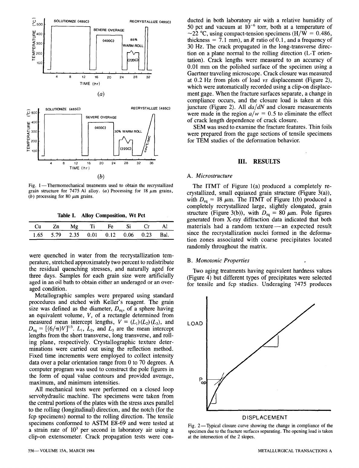
Starting with the 2.5 inch thick plate, two different inter-
mediate thermomechanical treatments (ITMT's), shown
schematically in Figure 1, were used to obtain the desired
grain structure. They include solutionizing, overaging,
warm rolling, and recrystallization treatments. The large
particles (-1 /xm diameter) that result from the overaging
treatment create strain concentrations during the warm roll-
ing, and these deformation zones act as nucleation sites for
recrystallization. 13 Small grains were obtained by using a
large amount of deformation and rapid heating to the re-
crystallization temperature (Figure l(a)). Large grains were
obtained by using a small amount of deformation and slow
heating to the recrystallization temperature (Figure l(b)).
All heat treatments were conducted in a molten nitride salt
bath except those associated with the rolling operation
which were conducted in an electric air furnace. Samples
METALLURGICAL TRANSACTIONS A VOLUME 15A, MARCH 1984--555
o•500
w 400
E~
~
300
n,-
w 200
w
I- 100
SOLUTIONIZE (485C)
m
i i i i i
4 8 12
TIME
RECRYSTALLIZE (485C)
SEVERE OVERAGE
I I I I I I I
16 20 24 28 32
(hr)
(a)
TIME (hr)
(b)
Fig. 1--Thermomechanical treatments used to obtain the recrystallized
grain structure for 7475 AI alloy. (a) Processing for 18/xm grains,
(b) processing for 80/zm grains.
SOLUTIONIZE (485C) RECRYSTALLIZE (485C)
SEVERE OVERAGE
.ooc, I /
7
i i i t I i 1 i i i i 218 i 2 / i
4 8 12 16 20 24 3 36
Table I. Alloy Composition, Wt Pct
B. Monotonic Properties
Cu Zn Mg Ti Fe Si Cr A1
1.65 5.79 2.35 0.01 0.12 0.06 0.23 Bal.
were quenched in water from the recrystallization tem-
perature, stretched approximately two percent to redistribute
the residual quenching stresses, and naturally aged for
three days. Samples for each grain size were artificially
aged in an oil bath to obtain either an underaged or an over-
aged condition.
Metallographic samples were prepared using standard
procedures and etched with Keller's reagent. The grain
size was defined as the diameter, Deq, of a sphere having
an equivalent volume, V, of a rectangle determined from
measured mean intercept lengths, V = (L1)(L2)(L3), and
Oeq :
[(6/'tr)V] 1/3.
LI, L2, and L 3 are the mean intercept
lengths from the short transverse, long transverse, and roll-
ing plane, respectively. Crystallographic texture deter-
minations were carried out using the reflection method.
Fixed time increments were employed to collect intensity
data over a polar orientation range from 0 to 70 degrees. A
computer program was used to construct the pole figures in
the form of equal value contours and provided average,
maximum, and minimum intensities.
All mechanical tests were performed on a closed loop
servohydraulic machine. The specimens were taken from
the central portions of the plates with the stress axes parallel
to the rolling (longitudinal) direction, and the notch (for the
fcp specimens) normal to the rolling direction. The tensile
specimens conformed to ASTM E8-69 and were tested at
a strain rate of 103 per second in laboratory air using a
clip-on extensometer. Crack propagation tests were con-
ducted in both laboratory air with a relative humidity of
50 pct and vacuum at
10 -6 tOIT,
both at a temperature of
-22 ~ using compact-tension specimens (H/W = 0.486,
thickness = 7.1 mm), an R ratio of 0.1, and a frequency of
30 Hz. The crack propagated in the long-transverse direc-
tion on a plane normal to the rolling direction (L-T orien-
tation). Crack lengths were measured to an accuracy of
0.01 mm on the polished surface of the specimen using a
Gaertner traveling microscope. Crack closure was measured
at 0.2 Hz from plots of load vs displacement (Figure 2),
which were automatically recorded using a clip-on displace-
ment gage. When the fracture surfaces separate, a change in
compliance occurs, and the closure load is taken at this
juncture (Figure 2). All da/dN and closure measurements
were made in the region a/w = 0.5 to eliminate the effect
of crack length dependence of crack closure.
SEM was used to examine the fracture features. Thin foils
were prepared from the gage sections of tensile specimens
for TEM studies of the deformation behavior.
III. RESULTS
A. Microstructure
The ITMT of Figure l(a) produced a completely re-
crystallized, small equiaxed grain structure (Figure 3(a)),
with Deq = 18/zm. The ITMT of Figure l(b) produced a
completely recrystallized large, slightly elongated, grain
structure (Figure 3(b)), with Deq = 80/xm. Pole figures
generated from X-ray diffraction data indicated that both
materials had a random texture--an expected result
since the recrystallization nuclei formed in the deforma-
tion zones associated with coarse precipitates located
randomly throughout the matrix.
LOAD
Two aging treatments having equivalent hardness values
(Figure 4) but different types of precipitates were selected
for tensile and fcp studies. Underaging 7475 produces
I
%
~
w
CI~ 400
:3
I--
C~..< 300
W
t~
3~ 200
I,.-
100
DISPLACEMENT
Fig. 2--Typical closure curve showing the change in compliance of the
specimen due to the fracture surfaces separating. The opening load is taken
at the intersection of the 2 slopes.
556--VOLUME 15A, MARCH 1984 METALLURGICAL TRANSACTIONS A
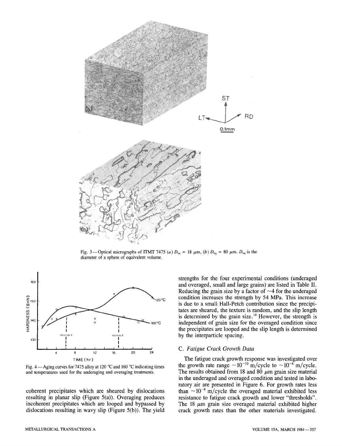
Fig. 3--Optical micrographs of ITMT 7475 (a) Deq = 18 p.m, (b) Deq = 80/zm. Deq is the
diameter of a sphere of equivalent volume.
160
Z
120oC
3Z150
co
w
~
140
rr
< I
-1- I I
UN[I~
[IAI [:
()V[ RA(;E
I I
130
I I
I I ~ I I I I I I I I I I
a
4
8 12
16
20 24
TIME(hr)
Fig. 4--Aging curves for 7475 alloy at 120 ~ and 160 ~ indicating times
and temperatures used for the underaging and overaging treatments.
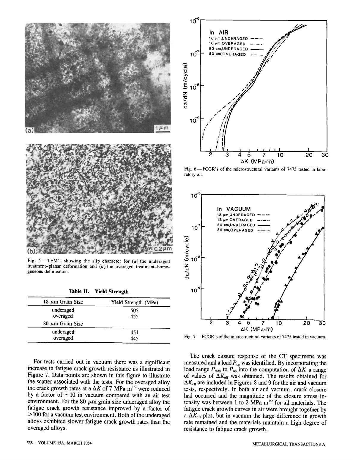
coherent precipitates which are sheared by dislocations
resulting in planar slip (Figure 5(a)). Overaging produces
incoherent precipitates which are looped and bypassed by
dislocations resulting in wavy slip (Figure 5(b)). The yield
strengths for the four experimental conditions (underaged
and overaged, small and large grains) are listed in Table II.
Reducing the grain size by a factor of -4 for the underaged
condition increases the strength by 54 MPa. This increase
is due to a small Hall-Petch contribution since the precipi-
tates are sheared, the texture is random, and the slip length
is determined by the grain size. 14 However, the strength is
independent of grain size for the overaged condition since
the precipitates are looped and the slip length is determined
by the interparticle spacing.
C. Fatigue Crack Growth Data
The fatigue crack growth response was investigated over
the growth rate range -10 -1~ m/cycle to
~10 -6
m/cycle.
The results obtained from 18 and 80/xm grain size material
in the underaged and overaged condition and tested in labo-
ratory air are presented in Figure 6. For growth rates less
than -10 -8 m/cycle the overaged material exhibited less
resistance to fatigue crack growth and lower "thresholds".
The 18/zm grain size overaged material exhibited higher
crack growth rates than the other materials investigated.
METALLURGICAL TRANSACTIONS A VOLUME 15A, MARCH 1984--557
10- 6
16 7
A
o
o
v E I(~ 8
Z
"0
"o
In AIR
18 #m,UNDERAGED mm
18 #m,OVERAGED
80 #m,UNDERAGED
80#m,OVERAGED
/
f ~ ,,
' : ' I
m
I
,
, I I I
2 3 4 5 7 10 20 30
,&K (MPa,/~)
Fig. 6--FCGR's of the microstructural variants of 7475 tested in labo-
ratory air.
Fig. 5--TEM's showing the slip character for (a)the underaged
treatment-planar deformation and (b)the overaged treatment-homo-
geneous deformation.
Table II. Yield
Strength
18/zm Grain Size Yield Strength (MPa)
underaged 505
overaged 455
80/zm Grain Size
underaged 451
overaged 445
1 1~61
In VACUUM ~,. "~':,~
18/,tm,UNDERAGED ~--~ ~.-'~:);~'
18 /~m.OVERAGED ..... ,~, ...~Jw/--
80 /arn,UNDERAGED ~"::,/~/I
16
"t
- 80 ~,OvE~,AGEO
........... .*" ~ ,"
Av =
f;.,,
.r
E 16a-
"" o ~',g e,6
Z /d_e"
=- ~ / tA ,/
J'f ,
~f ,~ , , , , 41 t
3 4 5 7 10 20 30
AK (MPaV~)
Fig, 7--FCGR's of the microstructural variants of 7475 tested in vacuum.
For tests carried out in vacuum there was a significant
increase in fatigue crack growth resistance as illustrated in
Figure 7. Data points are shown in this figure to illustrate
the scatter associated with the tests. For the overaged alloy
the crack growth rates at a AK of 7 MPa m 1/2 were reduced
by a factor of -10 in vacuum compared with an air test
environment. For the 80/xm grain size underaged alloy the
fatigue crack growth resistance improved by a factor of
> 100 for a vacuum test environment. Both of the underaged
alloys exhibited slower fatigue crack growth rates than the
overaged alloys.
The crack closure response of the CT specimens was
measured and a load Pop was identified. By incorporating the
load range
Pmax
to Pop into the computation of AK a range
of values of AKoff was obtained. The results obtained for
AKeff are included in Figures 8 and 9 for the air and vacuum
tests, respectively. In both air and vacuum, crack closure
had occurred and the magnitude of the closure stress in-
tensity was between 1 to 2 MPa m 1/2 for all materials. The
fatigue crack growth curves in air were brought together by
a AKeff plot, but in vacuum the large difference in growth
rate remained and the materials maintain a high degree of
resistance to fatigue crack growth.
558--VOLUME 15A, MARCH 1984 METALLURGICAL TRANSACTIONS A
ld 6
16 7
0
>,
0
16 8
Z
"O
15 g
In AIR
18 #m,UNDERAGED ------ ~"~"
18 ,arn.OVER A G ED ..... :..'-;
80 #m.UNDERAGED
80 ,um,OVERAGED ........... ,
,,.,-
,,.,-
,,.,-
~,Y
#,.
/..'."
~.'..
~/..."
./.
, , , , ,I I
) 3 7 lo 2o
AKeff (MPav~)
30
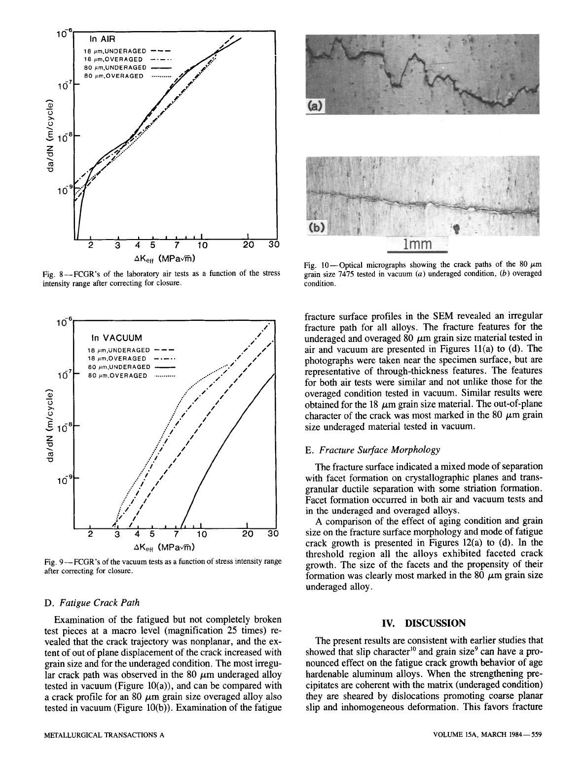
Fig. 8--FCGR's of the laboratory air tests as a function of the stress
intensity range after correcting for closure.
Fig. 10--Optical micrographs showing the crack paths of the 80/~m
grain size 7475 tested in vacuum (a) underaged condition, (b) overaged
condition.
10-6 In VACUUM
/.//~,]
18 ,um,UNDERAGED ------ /" / I
18 #m OVERAGED .....
/'"
// I
' ./ /
80 #rn,UNDERAGED ..-'" 9 . I
1 (~7 80 #m,OVERAGED ........... . ....... ".'/ /" 13
.-'""
i'' // /
_
"
/" //
/
~
/
(.)
:."
/./ //
~. ." . / /
// /
E
16 6 .'
/ /
/
"0
.:
/ /
.-'/" /
1 () 9 / " /
.:/.I //
::
i.I
ii ]l
-"/"
I /
./ i I
l
I ~'I /I I
, , , ~
I I
2 3 4 5 7 10 20 30
AKeff (MPa,/~)
Fig. 9-- FCGR's of the vacuum tests as a function of stress intensity range
after correcting for closure.
D. Fatigue Crack Path
Examination of the fatigued but not completely broken
test pieces at a macro level (magnification 25 times) re-
vealed that the crack trajectory was nonplanar, and the ex-
tent of out of plane displacement of the crack increased with
grain size and for the underaged condition. The most irregu-
lar crack path was observed in the 80/.~m underaged alloy
tested in vacuum (Figure 10(a)), and can be compared with
a crack profile for an 80/~m grain size overaged alloy also
tested in vacuum (Figure 10(b)). Examination of the fatigue
fracture surface profiles in the SEM revealed an irregular
fracture path for all alloys. The fracture features for the
underaged and overaged 80/zm grain size material tested in
air and vacuum are presented in Figures ll(a) to (d). The
photographs were taken near the specimen surface, but are
representative of through-thickness features. The features
for both air tests were similar and not unlike those for the
overaged condition tested in vacuum. Similar results were
obtained for the 18/xm grain size material. The out-of-plane
character of the crack was most marked in the 80/~m grain
size underaged material tested in vacuum.
E. Fracture Surface Morphology
The fracture surface indicated a mixed mode of separation
with facet formation on crystallographic planes and trans-
granular ductile separation with some striation formation.
Facet formation occurred in both air and vacuum tests and
in the underaged and overaged alloys.
A comparison of the effect of aging condition and grain
size on the fracture surface morphology and mode of fatigue
crack growth is presented in Figures 12(a) to (d). In the
threshold region all the alloys exhibited faceted crack
growth. The size of the facets and the propensity of their
formation was clearly most marked in the 80/~m grain size
underaged alloy.
IV. DISCUSSION
The present results are consistent with earlier studies that
showed that slip character 1~ and grain size 9 can have a pro-
nounced effect on the fatigue crack growth behavior of age
hardenable aluminum alloys. When the strengthening pre-
cipitates are coherent with the matrix (underaged condition)
they are sheared by dislocations promoting coarse planar
slip and inhomogeneous deformation. This favors fracture
METALLURGICAL TRANSACTIONS A VOLUME 15A, MARCH 1984--559
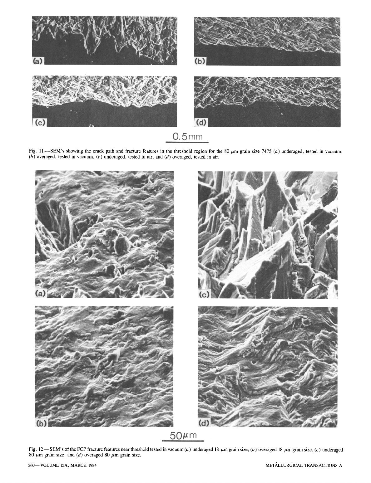
Fig. 11--SEM's showing the crack path and fracture features in the threshold region for the 80/zm grain size 7475 (a) underaged, tested in vacuum,
(b) overaged, tested in vacuum, (c) underaged, tested in air, and (d) overaged, tested in air.
Fig. 12-- SEM's of the FCP fracture features near threshold tested in vacuum (a) underaged 18 ~m grain size, (b) overaged 18/zm grain size, (c) underaged
80/zm grain size, and (d) overaged 80/~m grain size.
560--VOLUME 15A, MARCH 1984 METALLURGICAL TRANSACTIONS A
along slip planes and the occurrence of zigzag crack growth
and crack branching. When the strengthening precipitates
are incoherent with the matrix (overaged condition), they
are looped and bypassed by dislocations promoting more
homogeneous deformation and reducing crack tortuosity. A
reduction in grain size (by enhancing multiple slip at low
AK's 9)
and an aggressive environment (by decreasing the
plasticity needed for fracture 15) can also reduce crack tor-
tuosity although the oxides formed in air can have an op-
posite effect on crack growth rates by contributing a closure
component9 The slower crack growth rates associated with
planar slip and large grains have been attributed to: (a) slip
being more reversible, 9 (b) the tortuosity of the crack path, 10
(c) the AK of zigzag and branched cracks being smaller than
the AK calculated assuming a single crack normal to the
stress axis, l~ and (d) enhanced closure associated with in-
creased surface roughness. 16
A reduction in grain size, overaging, and an air environ-
ment reduces the reversibility of slip and crack tortuosity.
Consequently, it is not surprising that the 18/zm grain size,
overaged material had the poorest fatigue resistance of all
the conditions studied. A comparison of Figures 6 and 8
suggests that the differences in fatigue crack growth rates for
the various materials may be related to the difference in the
extent of crack closure that they exhibited in the air environ-
ment. However, this is probably an oversimplification of
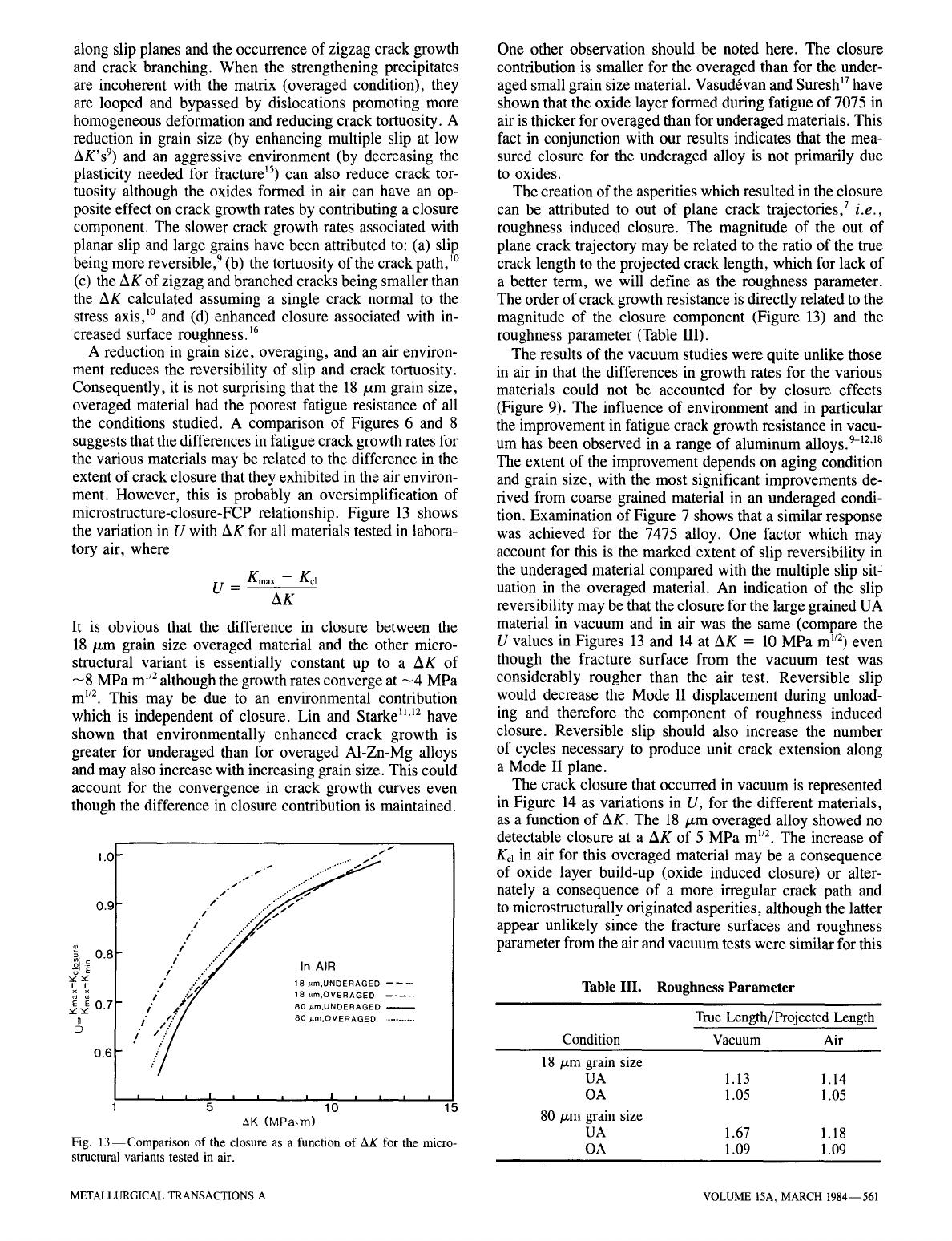
microstructure-closure-FCP relationship. Figure 13 shows
the variation in U with AK for all materials tested in labora-
tory air, where
Kmax --
Kcl
U-
AK
It is obvious that the difference in closure between the
18/zm grain size overaged material and the other micro-
structural variant is essentially constant up to a AK of
--8 MPa m 1/2 although the growth rates converge at -4 MPa
m 1/2. This may be due to an environmental contribution
which is independent of closure. Lin and Starke
TM
have
shown that environmentally enhanced crack growth is
greater for underaged than for overaged AI-Zn-Mg alloys
and may also increase with increasing grain size. This could
account for the convergence in crack growth curves even
though the difference in closure contribution is maintained9
lO f
,, 0.9
0.8
II
D
0.6
/
i" ..'"
9 ,.....
.I ... ~"
i I 9
/'/ ."'7 In AIR
i ~"://"~ 18 #m,UNOERAGED --~--
/" ,.-~/ 18 #m:OVERAGED .....
i ~'/~/ 80 #m,UNDERAGED
9
/.: 80 /~m,OVERAGED ~ 80 /~m,OVERAGED
...........
./ /..."
./
I I I I I I I I I I I I I
5 10 15
AK (MPa~)
Fig. 13--Comparison of the closure as a function of AK for the micro-
structural variants tested in air.
One other observation should be noted here. The closure
contribution is smaller for the overaged than for the under-
aged small grain size material. Vasudrvan and Suresh 17 have
shown that the oxide layer formed during fatigue of 7075 in
air is thicker for overaged than for underaged materials. This
fact in conjunction with our results indicates that the mea-
sured closure for the underaged alloy is not primarily due
to oxides9
The creation of the asperities which resulted in the closure
can be attributed to out of plane crack trajectories, 7
i.e.,
roughness induced closure. The magnitude of the out of
plane crack trajectory may be related to the ratio of the true
crack length to the projected crack length, which for lack of
a better term, we will define as the roughness parameter.
The order of crack growth resistance is directly related to the
magnitude of the closure component (Figure 13) and the
roughness parameter (Table III).
The results of the vacuum studies were quite unlike those
in air in that the differences in growth rates for the various
materials could not be accounted for by closure effects
(Figure 9). The influence of environment and in particular
the improvement in fatigue crack growth resistance in vacu-
um has been observed in a range of aluminum alloys. 9-1z'18
The extent of the improvement depends on aging condition
and grain size, with the most significant improvements de-
rived from coarse grained material in an underaged condi-
tion. Examination of Figure 7 shows that a similar response
was achieved for the 7475 alloy. One factor which may
account for this is the marked extent of slip reversibility in
the underaged material compared with the multiple slip sitZ
uation in the overaged material. An indication of the slip
reversibility may be that the closure for the large grained UA
material in vacuum and in air was the same (compare the
U values in Figures 13 and 14 at AK = 10 MPa m 1/2) even
though the fracture surface from the vacuum test was
considerably rougher than the air test. Reversible slip
would decrease the Mode II displacement during unload-
ing and therefore the component of roughness induced
closure. Reversible slip should also increase the number
of cycles necessary to produce unit crack extension along
a Mode II plane.
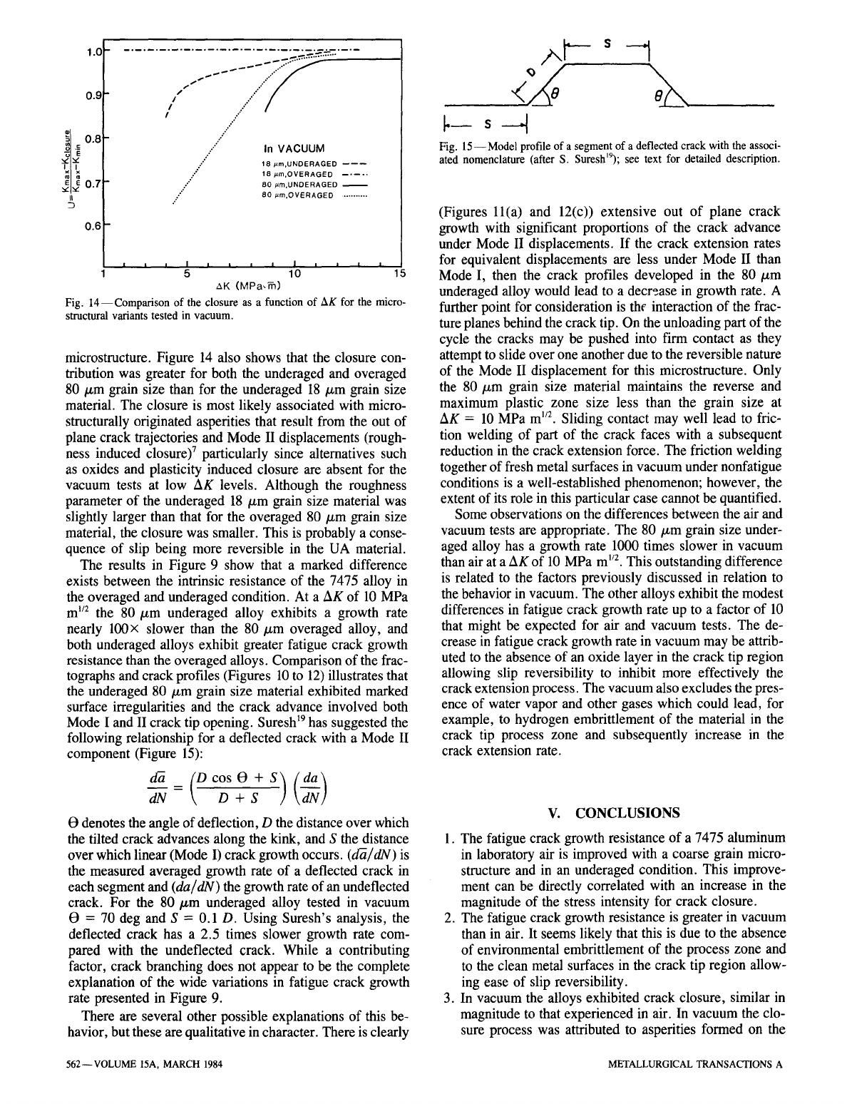
The crack closure that occurred in vacuum is represented
in Figure 14 as variations in U, for the different materials,
as a function of AK. The 18 /xm overaged alloy showed no
detectable closure at a AK of 5 MPa m ~/2. The increase of
Kcl in air for this overaged material may be a consequence
of oxide layer build-up (oxide induced closure) or alter-
nately a consequence of a more irregular crack path and
to microstructurally originated asperities, although the latter
appear unlikely since the fracture surfaces and roughness
parameter from the air and vacuum tests were similar for this
Table IlL Roughness Parameter
True Length/Projected Length
Condition Vacuum Air
18/xm grain size
UA 1.13 1.14
OA 1.05 1.05
80 p,m grain size
UA 1.67 1.18
OA 1.09 1.09
METALLURGICAL TRANSACTIONS A VOLUME 15A, MARCH 1984--561
0.91.0
1 .............................. /, ,, ~.~ ~_ ~ i.~.~,~.~'--~- ....
i~ 0.8
o .-
"6 E
x x
m m
E E0. 7
D
0.6
l
..." In VACUUM
.,'
18 #m.UNDERAGED
----~
18 .am.OVERAGED
.," 80 #m.UNDERAGED
:." 80 #m,OVERAGED
...........
I | i i i I i
5 10
AK (MPa,~)
Fig. 14--Comparison of the closure as a function of AK for the micro-
structural variants tested in vacuum.
microstructure. Figure 14 also shows that the closure con-
tribution was greater for both the underaged and overaged
80 #m grain size than for the underaged 18/xm grain size
material. The closure is most likely associated with micro-
structurally originated asperities that result from the out of
plane crack trajectories and Mode II displacements (rough-
ness induced closure) 7 particularly since alternatives such
as oxides and plasticity induced closure are absent for the
vacuum tests at low AK levels. Although the roughness
parameter of the underaged 18/xm grain size material was
slightly larger than that for the overaged 80/zm grain size
material, the closure was smaller. This is probably a conse-
quence of slip being more reversible in the UA material.
The results in Figure 9 show that a marked difference
exists between the intrinsic resistance of the 7475 alloy in
the overaged and underaged condition. At a AK of 10 MPa
m 1/2 the 80/~m underaged alloy exhibits a growth rate
nearly 100x slower than the 80/xm overaged alloy, and
both underaged alloys exhibit greater fatigue crack growth
resistance than the overaged alloys. Comparison of the frac-
tographs and crack profiles (Figures 10 to 12) illustrates that
the underaged 80/xm grain size material exhibited marked
surface irregularities and the crack advance involved both
Mode I and II crack tip opening.
Suresh ~9
has suggested the
following relationship for a deflected crack with a Mode II
component (Figure 15):
-~ D+ S
t9 denotes the angle of deflection, D the distance over which
the tilted crack advances along the kink, and S the distance
over which linear (Mode I) crack growth occurs. (d~/dN) is
the measured averaged growth rate of a deflected crack in
each segment and
(da/dN)
the growth rate of an undeflected
crack. For the 80/zm underaged alloy tested in vacuum
19 = 70 deg and S = 0.1 D. Using Suresh's analysis, the
deflected crack has a 2.5 times slower growth rate com-
pared with the undeflected crack. While a contributing
factor, crack branching does not appear to be the complete
explanation of the wide variations in fatigue crack growth
rate presented in Figure 9.
There are several other possible explanations of this be-
havior, but these are qualitative in character. There is clearly
s J
I
Fig. 15--Model profile of a segment of a deflected crack with the associ-
ated nomenclature (after S. Sureshl9); see text for detailed description.
(Figures ll(a) and 12(c)) extensive out of plane crack
growth with significant proportions of the crack advance
under Mode II displacements. If the crack extension rates
for equivalent displacements are less under Mode II than
Mode I, then the crack profiles developed in the 80/zm
underaged alloy would lead to a decrease in growth rate. A
further point for consideration is the interaction of the frac-
ture planes behind the crack tip. On the unloading part of the
cycle the cracks may be pushed into firm contact as they
attempt to slide over one another due to the reversible nature
of the Mode II displacement for this microstructure. Only
the 80/xm grain size material maintains the reverse and
maximum plastic zone size less than the grain size at
AK = 10 MPa m '/2. Sliding contact may well lead to fric-
tion welding of part of the crack faces with a subsequent
reduction in the crack extension force. The friction welding
together of fresh metal surfaces in vacuum under nonfatigue
conditions is a well-established phenomenon; however, the
extent of its role in this particular case cannot be quantified.
Some observations on the differences between the air and
vacuum tests are appropriate. The 80/~m grain size under-
aged alloy has a growth rate 1000 times slower in vacuum
than air at a AK of 10 MPa m 1/2. This outstanding difference
is related to the factors previously discussed in relation to
the behavior in vacuum. The other alloys exhibit the modest
differences in fatigue crack growth rate up to a factor of 10
that might be expected for air and vacuum tests. The de-
crease in fatigue crack growth rate in vacuum may be attrib-
uted to the absence of an oxide layer in the crack tip region
allowing slip reversibility to inhibit more effectively the
crack extension process. The vacuum also excludes the pres-
ence of water vapor and other gases which could lead, for
example, to hydrogen embrittlement of the material in the
crack tip process zone and subsequently increase in the
crack extension rate.
V. CONCLUSIONS
1. The fatigue crack growth resistance of a 7475 aluminum
in laboratory air is improved with a coarse grain micro-
structure and in an underaged condition. This improve-
ment can be directly correlated with an increase in the
magnitude of the stress intensity for crack closure.
2. The fatigue crack growth resistance is greater in vacuum
than in air. It seems likely that this is due to the absence
of environmental embrittlement of the process zone and
to the clean metal surfaces in the crack tip region allow-
ing ease of slip reversibility.
3. In vacuum the alloys exhibited crack closure, similar in
magnitude to that experienced in air. In vacuum the clo-
sure process was attributed to asperities formed on the
562--VOLUME 15A, MARCH 1984 METALLURGICAL TRANSACTIONS A
fatigue fracture surfaces as a consequence of facet for-
mation and out of plane crack trajectories. An expected
large increase in closure due to a very large increase in
surface roughness for the 80 pm underaged material was
not observed due to the reversibility of the Mode II dis-
placement for this microstructure.
4. In vacuum the 80 pm grain size underaged alloy ex-
hibited highly irregular crack profiles and fatigue crack
growth rates up to 100 times slower than the 18/xm
underaged and 80/xm overaged materials. This high
degree of surface irregularity is attributed to the
coarse grain size and planar slip characteristics of the
underaged alloy.
5. The much greater fatigue crack growth resistance in
vacuum of the 80/xm underaged alloy is considered to be
a consequence of a number of factors including crack
branching, mixed Mode I and II crack advance, en-
hanced slip reversibility, and possibly welding of the
fracture surfaces on the unloading part of fatigue cycle.
ACKNOWLEDGMENTS
This research was sponsored by the Air Force Office
of Scientific Research, United States Air Force Systems
Command, under Grant AFOSR-83-0061, Dr. Alan H.
Rosenstein, program manager. We would like to thank
Dr. S. Suresh for fumishing us with a copy of his paper on
crack deflection prior to publication.
REFERENCES
1. J.E. Shigley: Mechanical Engineering Design, 1977, McGraw-Hill,
New York, NY, p. 179.
2. R.A. Smith: in Fatigue Thresholds, Fundamentals and Engineering
Applications, J. Biicklund, A. F. Blom, and C. J. Beevers, eds., Engi-
neering Materials Advisory Services, Ltd., West Midlands, UK, 1981,
vol. I, p. 33.
3. P. Stenvall: in Fatigue Thresholds, Fundamentals and Engineering
Applications, J. Biicklund, A. F. Blom, and C. J. Beevers, eds., Engi-
neering Materials Advisory Services, Ltd., West Midlands, UK, 1981,
vol. II, p. 931.
4. W. Elber: Eng. Fracture Mech., 1970, vol. 2, p. 37.
5. T.C. Lindley and C.E. Richards: Mat. Sci. Eng., 1974, vol. 14,
p. 381.
6. R.O. Ritchie, S. Suresh, and C. M. Moss: J. Eng. Mat. and Tech.,
Trans. ASME Series H, 1979, vol. 102, p. 293.
7. N. Walker and C.J. Beevers: Fat. of Eng. Mat. and Struct., 1979,
vol. 1, p. 135.
8. R.O. Ritchie and S. Suresh: Metall. Trans. A, 1978, vol. 9A, p. 291.
9. J. Lindigkeit, G. Terlinde, A. Gysler, and G. LiJtjering: Acta Metall.,
1979, vol. 27, p. 1717.
10. Fu-Shiong Lin and E. A. Starke, Jr.: Mat. Sci. Eng., 1980, vol. 43,
p. 65.
11. Fu-Shiong Lin and E. A. Starke, Jr.: Mat. Sci. Eng., 1980, vol. 45,
p. 153.
12. Fu-Shiong Lin and E.A. Starke, Jr.: in Hydrogen in Metals, A.W.
Thompson and I. M. Bernstein, eds., TMS-AIME, Warrendale, PA,
1981, p. 485.
13. John A. Wert, N.E. Paton, C.H. Hamilton, and M.W. Mahoney:
Metall. Trans. A, 1981, vol. 12A, p. 1267.
14. Edgar A. Starke, Jr.: Strength of Metals and Alloys (ICSMAG), R. C.
Gifkins, ed., Pergamon Press, Oxford, 1983, vol. 3, p. 1025.
15. J. Petit, B. Bouchet, C. Goss, and J. de Fouguet: Fracture, Proc. 4th
Int. Conf. on Fracture (ICF4), D. M. R. Taplin, ed., University of
Waterloo Press, Waterloo, Canada, 1977, vol. 2, p. 867.
16. M.D. Holliday and C. J. Beevers: Int. J. of Fracture, 1979, vol. 15,
p. R27.
17. A.K. Vasudrvan and S. Suresh: Metall. Trans. A, 1982, vol. 13A,
p. 2271.
18. B.R. Kirby and C. J. Beevers: Fatigue of Eng. Mat. and Structures,
1979, vol. 1, p. 203.
19. S. Suresh: Metall. Trans. A, 1983, vol. 14A, p. 2375.
METALLURGICAL TRANSACTIONS A VOLUME 15A, MARCH 1984--563
