
Fatigue Properties of Nitrided Ultrafine Ferrite-Cementite Steels
under Rotating Bending Fatigue Testing
Y. FURUYA, H. HIRUKAWA, S. MATSUOKA, S. TORIZUKA, and H. KUWAHARA
Fatigue tests under rotating bending were conducted on nitrided ultrafine ferrite-cementite
steels. The ultrafine ferrite-cementite steels included carbon-increased and phosphorus-added
versions to investiga te the effects of grain growth suppression during nitriding. In the carbon-
increased versions, grain growth was successfully suppressed both in the nitrided layer and in the
core region. On the other hand, the low-carbon versions showed grain growth in the core region,
even in the phosphoru s-added types, althoug h grain growth was suppresse d in the nitrided layer.
In the fatigue tests, many of the nitrided specimens revealed fish-eye fractures originating from
inclusions located in or beneath the nitrided layer. In spite of the occurrence of fish-eye frac-
tures, the fatigue strength of the carbon-increased versions was markedly impr oved due to
nitriding, whereas it was a little improved in the low-carbon versions. The fatigue strength of the
nitrided specimens was closely related to hardness at the fracture origin, even when fish-eye
fractures occurred. This was why nitriding markedly improved the fatigue strength of the car-
bon-increased versions in which grain growth was success fully suppressed and high ha rdness
was maintained beneath the nitrided layer.
DOI: 10.1007/s11661-008-9544-z
The Minerals, Metals & Materials Society and ASM International 2008
I. INTRODUCTION
GRAIN refinement is a logical way of strengthening
steel, because this process achieves high strength without
concomitantly increasing the ductile-to-brittle transition
temperature. Using the latest techniques, grain sizes can
be refined to below 1 lm. More specifically, several
research studies have succeeded in grain refinement that
yields submicron ferrite grains, starting from bulk
steel.
[1–3]
Our institute has also established a submicron
grain-refinement process using multipass warm caliber
rolling.
[4,5]
This process yields ultrafine-grained steel
bars that are thick and long enough to machine into
specimens for mechanical tests. The microstructure of
this ultrafine-grained steel is not ferrite-pearlite but
ferrite-cementite, so this ultrafine-grained steel is termed
ultrafine ferrite-cementite steel in this report.
Although many kinds of mechanical properties are
required of structural materials, fatigue strength is one
of the most important, because it is a frequently
required characteristic of mechanical components. This
has prompted research into fatigue strength in ultrafine
ferrite-cementite steel.
[6–8]
Previous studies have com-
pared ultrafine ferrite-cementite steel with conventional
tempered martensite and ferrite-pearlite steels.
[9,10]
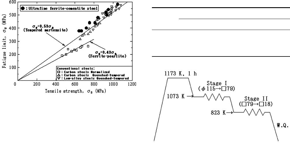
Although tempe red martensite steel showed higher
fatigue strength than ferrite-pearl ite steel, the fatigue
strength of ultrafine ferrite-cementite steel matched that
of tempered martensite, as seen in Figure 1. The reason
for this high degree of fatigue strength is that the
microstructure of ultrafine ferrite-cementite steel is not
only ultrafine but also uniform.
On the other hand, surface modification to harden the
surface is frequently conducted in steels destined for
machine structural use. Surface modification enhances
both fatigue strength and wear resistance. It is therefore
necessary to investigate the potential for surface mod-
ification of ultrafine ferrite-cementite steel. Typical
surface modification methods are carburizing, induction
hardening, and nitriding. Carburizing is, however, very
difficult to apply to ultrafine ferrite-cementite steel. In
this process , steels are held at high temperatures, above
1173 K, for a long time. At this temperature, transfor-
mation into austenite occurs, making it almost impos-
sible to preserve the ultrafine ferr ite grains. The
remaining choices were induction hardening or nitrid-
ing; for this study, we selected nitriding.
In nitriding, steels are held at temperatures ranging
from 773 to 873 K for a long time. In this temperature
range, grain growth of ferrite grains, but never trans-
formation, can take place. Suppression of grain growth
is thus the key to nitriding ultrafine ferrite-cementite
steel. In nitrided steels, fish-eye fractures frequently
occur, even beneath the nitrided layer,
[11,12]
so grain
growth needs to be suppressed in the core region as well
as in the nitrided layer. One effective way of suppressing
grain growth is to pin the grain boundaries. In our
previous research,
[8]
cementite particles revealed strong
Y. FURUYA and H. HIRUKAWA, Senior Researchers, and
S. TORIZUKA, Group Leader, are with the National Institute for
Materials Science, 1-2-1 Sengen, Tsukuba, Ibaraki 305-0047, Japan.
formerly Deputy Director General, with the National Institute for
Materials Science, 1-2-1 Sengen, Tsukuba, Ibaraki 305-0047, Japan, is
Professor, Department of Mechanical Engineering, Faculty of
Engineering, Kyushu University, 744 Motooka, Nishi-ku, Fukuoka
819-0395, Japan. H. KUWAHARA, Vice President, is with the
Research Institute for Applied Science, Tanaka Ohicho, Sakyo-ku,
Kyoto 606-8202, Japan.
Manuscript submitted December 27, 2007.
Article published online May 7, 2008
2068—VOLUME 39A, SEPTEMBER 2008 METALLURGICAL AND MATERIALS TRANSACTIONS A
pinning effects in ultrafine ferrite-cementite steel, sup-
pressing grain growth during annealing. In ultrafine
ferrite-cementite steel, raising the carbon content
resulted in increased numbers of cementite particles,
and the carbon-increased version showed negligible
grain growth even during 30-hour annealing at 773 K.
Moreover, in that study, phosphorus addition also
showed the effects of grain growth suppression while
annealing the ultrafine ferrite-cementite steel. This effect
was likely to be a type of solute drag.
[13,14]
In this study, fatigue strength was investigated in
nitrided ultrafine ferrite-cementite steel. The fatigue tests
were conducted under rotating bending. In general ,
surface-hardened steels are used under conditions where
high stress acts on and around the surface, so the
rotating bending fatigue testing is closer to actual use
than the axial loading fatigue testing. The effects of grain
growth suppression were investigated by conducting
fatigue tests on the carbon-increased and phosphorus-
added versions of the nitrided ultrafine ferrite-cementite
steels. The ultrafine ferrite-cementite steels used in this
study were the same as in our previous investigation.
[8]
II. EXPERIMENTAL PROCEDURE
A. Preparation of Materials
Table I shows the chemical composition of the steels.
15C is a base steel containing about 0.15 pct (as mass
pct) carbon. 45C, containing about 0.45 pct carbon, is a
version made to investigate the effect of grain growth
suppression due to the presence of cementite particles
during nitriding. 15C-P steel, containing about 0.1 pct
phosphorus, was used to investigate the grain growth
suppressive effect of phosphorus addition. 45C-P steel, to
which both carbon and phosphorus had been added, was
a version designed to investigate their multiple effects.
Ingots of these steels were melted under vacuum on a
laboratory scale and forged into round bars 115 mm in
diameter. Submicron grain refinement was then con-
ducted using multipass warm caliber rolling.
[4]
Figure 2
shows the submicron grain-refinement process. Stage I
comprised hot caliber rolling at 1073 K to form 79-mm-
square bars. Stage II, resulting in 18-mm-square bars,
comprised multipass warm caliber rolling to refine the
ferrite grains. The accumulated reduction of the cross-
sectional area in stage II was 95 pct, and the 18-mm-
square bars were water cooled immediately after the
warm caliber rolling.
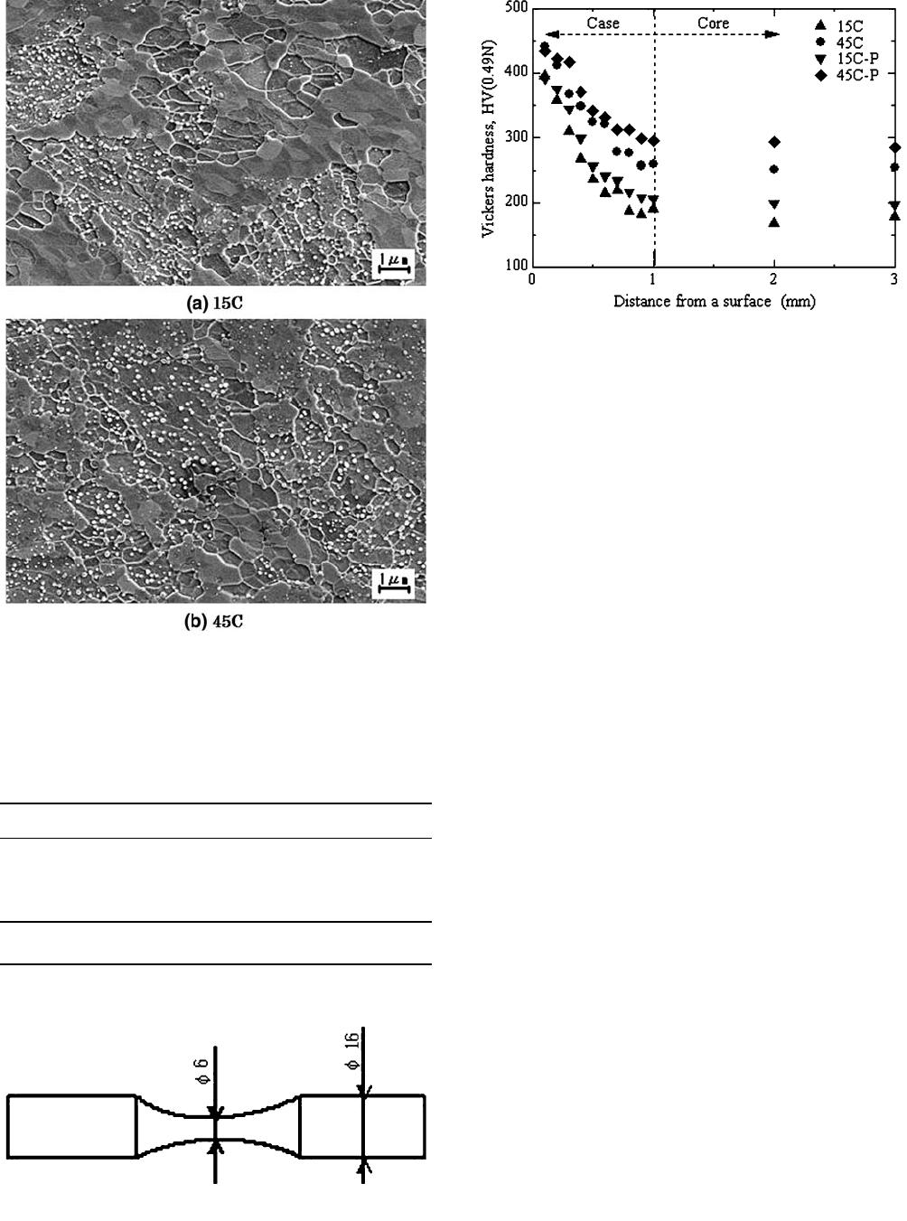
Figure 3 shows the microstructure of the ultrafine
ferrite-cementite steels. Although only 15C and 45C are
shown, the microstructures of 15C-P and 45C-P are
similar to those of 15C and 45C, respectively. The 45C
carbon-increased version reveals dense cementite parti-
cles. Table II shows the mechanical properties and
nominal ferrite grain sizes of the ultrafine ferrite-
cementite steels. The tensile strengths range from 842
to 1048 MPa, and the ferr ite grain sizes are about
0.4 lm, regardless of version.
B. Fatigue Test Specimen and Nitriding Condition
Figure 4 shows a fatigue test specimen. The specimens
were hourglass shaped with a diameter of 6 mm at the
minimum section. After machining to this shape, plasma
nitriding
[15–17]
was conducted at 773 K for 16 hours,
followed by water cooling. After this plasma nitriding,
the narrowed section of the specimens was repolished,
removing 0.1 mm of the surface layer. As a result, the
diameter of the nitrided specimens was 5.8 mm at the
minimum section when the fatigue tests were conducted.
The surface of the minimum section was finally polished
in the axial direction with 600-grit paper.
C. Microstructure Observation and Mechanical Tests
The microstructures of the nitrided specimens were
observed using a field emission– scanning electron
Table I. Chemical Compositions of the Steels
Steel
Element (Mass Pct)
CSiMn P S
15C 0.14 0.31 1.51 0.001 0.0006
45C 0.43 0.31 1.50 <0.001 0.0009
15C-P 0.14 0.30 1.48 0.093 0.0007
45C-P 0.45 0.30 1.49 0.10 0.0011
Fig. 2—Schematic illustration of the caliber rolling process.
Fig. 1—Fatigue limits of the ultrafine ferrite-cementite steels
[8]
plot-
ted against tensile strength, together with conventional tempered
martensite and ferrite-pearlite steels.
METALLURGICAL AND MATERIALS TRANSACTIONS A VOLUME 39A, SEPTEMBER 2008—2069
microscope (FE-SEM). These observations were
conducted on the electropolished surfaces
[18]
of cross
sections. Nominal ferrite grain sizes were measured
using the FE-SEM images according to ASTM stan-
dards.
[19]
The mechanical tests conducted were Vickers hard-
ness and rotating bending fatigue tests. The Vickers
hardness was measured at 0.49 N on mirror-polished
surfaces of cross sections. The rotating bending fatigue
tests were conducted at 120 Hz up to 10
8
cycles. The
fatigue tests were conducted at room temperature in air.
The fracture surface after fatigue tests was observed
with FE-SEM, and in the case of fish-eye fractures, the
origin was analyzed by energy-dispersive atomic X-rays
(EDAX).
III. EXPERIMENTAL RESULTS
A. Hardness Distribution and Microstructure of Nitrided
Specimens
Figure 5 shows Vickers hardness distributions of the
nitride specimens. These hardness distributions were
measured in the grip section of the nitrided specimens,
whose surface had not been polished after the nitriding.
The hardness at 0.1 mm distance from the surface thus
corresponds to that at the surface of the narrowed
section, because the 0.1-mm surface layer of the nar-
rowed section was removed by polishing after nitriding.
The hardness at 3-mm distance from the surface
therefore corresponds to that at the center of the
narrowed section.
These hardness distributions revealed that the case
depth, i.e., the depth of the nitrided layer, was about
1 mm. No plateau region was observed, regardless of
the version of the ultrafine ferrite-cementite steel. The
hardness at the surface of the narrowed section ranged
from HV391 to HV441: a little higher in 45C and 45C-P
than in 15C and 15C-P. The difference in the hardness
was more marked in the core region, i.e., beneath the
Fig. 3—Microstructures of the ultrafine ferrite-cementite steels
before nitriding.
[8]
Table II. Mechanical Properties and Nominal Ferrite Grain
Sizes of the Ultrafine Ferrite-Cementite Steels before
Nitriding
[8]
Steel r
y
(MPa) r
B
(MPa) d (Pct) HV dn (lm)
15C 829 842 17 286 0.45
45C 920 952 17 300 0.43
15C-P 926 926 13 308 0.43
45C-P 1020 1048 15 339 0.44
r
y
: lower yield strength, r
B
: tensile strength, d: total elongation,
HV: Vickers hardness, and dn: nominal ferrite grain size.
Fig. 4—Profiles of a fatigue test specimen in millimeters.
Fig. 5—Vickers hardness distributions of nitrided specimens from
surface to center.
2070—VOLUME 39A, SEPTEMBER 2008 METALLURGICAL AND MATERIALS TRANSACTIONS A
nitrided layer. The hardness at the center ranged from
HV178 to HV286. When the hardn ess at the center was
compared with that before nitriding, the reduction of
hardness during nitriding was about HV110 in 15C and
15C-P, in contrast to about HV50 in 45C and 45C-P.
The decline in hardness in the core region was thus very
high in the 15C and 15C-P steels.
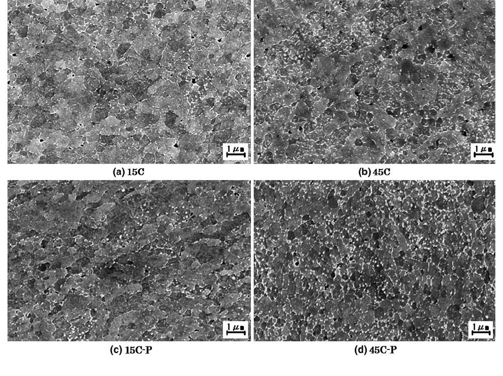
Figures 6 and 7 show microstructures of the nitrided
layer and the core region, respectively. These micro-
structures were also observed in the grip section of the
nitrided specimens. Figure 6 shows the microstructures
observed at 0.1 mm below each surface, so these
microstructures correspond to those at the surface of
the narrowed section. The microstructures in Figure 7,
observed at 3 mm below the surface, similarly corre-
spond to those at the center.
The ferrite grains in the nitrided layer remained
ultrafine regardless of the version of the ultrafine ferr ite-
cementite steel. Fine precipitates, which were not
observed before the nitriding, were observed around
the grain boundaries. These fine precipitates were
reduced in proportion to increasing distance from the
surface, and accordingly, ferrite grain sizes were
increased in 15C and 15C-P. Although these precipitates
were too fine to allow identification of their chemical
compositions by EDAX, they were assumed to be
nitrides.
The ferrite grains in the core region showed significant
growth in 15C and 15C-P, while grain growth was
negligible in 45C a nd 45C-P. The nominal ferrite grain
sizes in the core region were 4.4 lm in 15C, 0.7 lmin
45C, 2.6 lm in 15C-P, and 0.7 lm in 45C-P. In the
carbon-increased versions, thus, grain growth during
nitriding was successfully suppressed, and somewhat
suppressed in the phosphorus-added versi on.
B. Fatigue Test Results
Figure 8 shows the fatigue test results of 15C and
15C-P, comparing the nitrided specimens with the
as-rolled specimens, i.e., specimens without nitriding. The
nitrided specimens showed fish-eye fractures that did not
occur in the as-rolled specimens. The fish-eye fracture
tended to occur at lower stress amplitudes and longer
fatigue lives. This trend was similar to a stepwise S-N
curve in gigacycle fatigue of high-strength steel.
[20]
The
fish-eye fracture origins were located in or beneath the
nitrided layer. The nitrided specimens revealed higher
fatigue strength at above 10
6
cycles than the as-rolled
specimens, while the degree of improvement was small.
Fig. 6—Microstructures of the nitrided layer, observed on the electropolished surfaces of a cross section using FE-SEM.
METALLURGICAL AND MATERIALS TRANSACTIONS A VOLUME 39A, SEPTEMBER 2008—2071
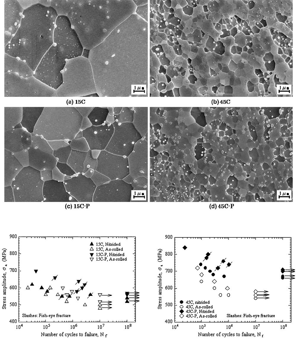
When the fatigue strength was compared between 15C
and 15C-P for the nitrided specimens, the 15C-P showed
slightly higher fatigue strength.
Figure 9 shows fatigue test results for the 45C and
45C-P nitrided specimens, together with the as-rolled
specimens. In 45C and 45C-P, only the 45C-P nitrided
specimens showed fish-eye fractures. The fish-eye
fracture origins were also located in or beneath the
nitrided layer. In both 45C and 45C-P, the nitrided
specimens revealed much higher fatigue strength than
Fig. 7—Microstructures of the core region, observed on the electropolished surface of a cross section using FE-SEM.
Fig. 8—Fatigue test results from the nitrided 15C and 15C-P speci-
mens, together with those for as-rolled specimens, i.e., specimens
without nitriding.
[8]
Fig. 9—Fatigue test results using the nitrided 45C and 45C-P
specimens, together with those using as-rolled specimens, i.e., non-
nitrided specimens.
[8]
2072—VOLUME 39A, SEPTEMBER 2008 METALLURGICAL AND MATERIALS TRANSACTIONS A
the as-rolled specimens. When the fatigue strength was
compared between the nitrided 45C and 45C-P speci-
mens, 45C-P showed clearly higher fatigue strength.
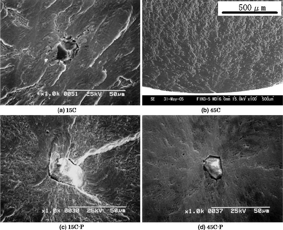
Figure 10 shows typical fracture surfaces of the
nitrided specimens. Most fish-eye fracture origins were
an Al
2
O
3
inclusion, as seen in Figures 10(a) through (d),
while in some fish-eye fracture surfaces, no inclusions
were identified at the origin. In 45C, only surface
fractures occurred, as seen in Figure 10(b). The Al
2
O
3
inclusion sizes ranged from 13 to 34 lm regardless of the
version of the ultrafine ferrite-cementite steel. Distances
from the surface to the fish-eye fracture origin ranged
from 0.35 to 1.05 mm.
IV. DISCUSSION
A. Nitriding of the Ultrafine Ferrite-Cementite Steel
One of the key points in nitriding ultrafine ferrite-
cementite steel is how to suppress grain growth during
the process. This suppression of grain growth should be
achieved both in the nitrided layer and in the core
region. In the nitrided layer, grain growth was negligi-
ble, regardless of the version of ultrafine ferrite-cement-
ite steel, as seen in Figure 6. In the nitride layer, fine
nitrides, precipitated during nitriding, reveal a pinning
effect on the grain boundaries at the same time. Thus,
grain growth during nitriding is automatically sup-
pressed in the nitrided layer. The key point here is
suppression of grain growth in the core region.
The ferrite grain sizes in the core region of the nitrided
specimens showed a marked difference between versions
of the ultrafine ferrite-cementite steels, as seen in
Figure 7. In 45C and 45C-P, the grain growth in the
core region was successfully suppressed, unlike in 15C
and 15C-P. This is due to the pinning effect of dense
cementite particles. Namely, the pinning effect of the
dense cementite particles is strong enough to suppress
grain growth during nitriding. A sufficiently strong
pinning effect is expected to appear in the other
precipitated particles, because the grain growth in the
Fig. 10—Typical FE-SEM fractographs of the nitrided specimens at around the fracture origin. (a) 15C broken at 1.2 · 10
5
cycles at 580 MPa,
(b) 45C broken at 4.9 · 10
5
cycles at 670 MPa, (c) 15C-P broken at 1.6 · 10
6
cycles at 640 MPa, and (d) 45C-P broken at 1.0 · 10
6
cycles at
740 MPa.
METALLURGICAL AND MATERIALS TRANSACTIONS A VOLUME 39A, SEPTEMBER 2008—2073

nitrided layer is similarly suppressed by fine nitrides. In
conclusion, this study demon strates that using the
pinning effect of precipitated particles effectively sup-
presses grain growth during nitriding.
Phosphorus addition also resulted in suppression of
the grain growth. The ferrite grain sizes in the core
region of the nitrided specimens were smaller in the
15C-P than in the 15C. This is due to a type of solute-
drag effect.
[13,14]
However, this effect, which is due to
0.1 pct phosphorus addition, is not strong enough to
sufficiently suppress grain growth during nitriding,
because the ferrite grain size in the core region of the
15C-P specimens was enlarged up to 2.6 lm. Conse-
quently, addition of phosphorus is not as effective as
using the pinning effect of precipitated particles to
suppress grain growth during nitriding.
On the other hand, the details of the fine nitrides
observed in the nitrided layer were not identified in this
study. Based on the chemical compositions in Table I,
elements able to form fine nitrides are Fe, Si, and Mn.
Of these elements, Fe can be excluded. Ferrous nitrides
are formed in an external nitriding layer, i.e.,a
composite layer, which is the outer region of the nitrided
layer that is normally a few tens of microns thick after
plasma nitriding.
[16,17]
However, 0.1 mm of the surface
layer was removed by polishing, so in this study, the
external nitriding layer was completely removed. More-
over, 0.3 pct Si is not able to increase the hardness in the
internal nitriding layer, i.e., the diffusion layer.
[21,22]
0.3 pct of Si is too little to increase Vickers hardness so
much as to be seen in Figure 5. Therefore, the fine
nitrides are the most likely to be manganese nitrides.
B. Fatigue Strength of the Nitrided Ultrafine
Ferrite-Cementite Steel
The fatigue test results of this study are summarized
in Table III. Improvements of the fatigue limit due to
nitriding are 120 MPa in 45C and 45C-P, while they are
from 40 to 60 MPa in 15C and 15C-P. The fatigue limits
of the nitrided specimens appear to be more closely
related to the Vickers hardness in the core region than
that at the surface. To investigate the effect of hardness,
more detailed analysis is necessary, because fish-eye
fractures occur in the nitrided specimens. If a fish-eye
fracture occurs under rotating bending, local stress
amplitudes at the fracture origin are smaller than the
nominal stress amplitude due to the stress gradie nt.
Moreover, the hardness of the nitrided specimens varies
from the surface to the core region. Therefore, relation-
ships between the local stress amplitude and the
hardness at the fracture origin must be taken into
account when investigating the effect of hardness.
Figure 11 shows a r
a
c
/HV
c
vs N
f
diagram for nitrided
and as-rolled specimens of 15C, 45C, 15C-P, and 45C-P.
In this diagram, the local stress amplitude, r
a
c
,is
normalized with Vickers hardness, HV
c
, at the fracture
origin. In this formulation, the results of the as-rolled
specimens show a unique curve, reducing the difference
between the versions of the ultrafine ferrite-cementite
steel. This means that the hardness of the matrix is a
major factor that controls the fatigue strength of
ultrafine ferrite-cementite steel. On the other hand, the
results for the nitrided specimens show large scattering,
even in this formulation. In the nitrided specimens, the
results that end in fish-eye fracture, which themselves
show large scattering, are distributed in a higher fatigue
strength region than those ending in surface fracture.
Based on Figure 11, the fatigue strength of the nitrided
ultrafine ferrite -cementite steel will be discussed subse-
quently.
Many of the results ending in fish-eye fracture show
good agreement with the results for the as-rolled
specimens, although a few of the results are distributed
in a somewhat higher fatigue strength region. This
suggests that an effect of hardness is large on fatigue
strength, even in case of fish-eye fractures occurring in
the nitrided specimens. In the case of surface fracture,
hardness of the matrix is a dominant factor in fatigue
strength, as mentioned previously. However, in the case
of fish-eye fracture, the dominant factor is the inclusion
size at the fracture origin, and past research on high-
strength steels whose tensile strength exceeded
1500 MPa suggested that the effect of hardness was
small.
[23–25]
In contrast, the present results suggest that
the hardness at the fracture origin is also a factor in the
case of fish-eye fracture of the nitrided ultrafine ferrite-
cementite steel. Therefore, to achieve high fatigue
strength in nitrided ultrafine ferrite-cementite steel,
maintaining high hardness beneath the nitrided layer is
Table III. Fatigue Limits and Vickers Hardness of the
Nitrided Specimens
Steel
Vickers Hardness* Fatigue Limit (MPa)
Surface Core As-Rolled Nitrided
15C 396 140 480 540
45C 441 243 540 660
15C-P 391 174 520 560
45C-P 435 283 580 700
*Vickers hardness of the nitrided specimens.
Fig. 11—r
a
c
/HV
c
vs N
f
diagram. Both r
a
c
and HV
c
indicate the local
stress amplitude and Vickers hardness at the fracture origin.
2074—VOLUME 39A, SEPTEMBER 2008 METALLURGICAL AND MATERIALS TRANSACTIONS A
necessary, as well as increasing the hardness in the
nitrided layer, because fish-eye fractures occur both in
and beneath the nitrided layer. Thus, the fatigue
strengths of 45C and 45C-P were distinctly improved
by nitriding; i.e., 45C and 45C-P successfully main-
tained high hardness beneath the nitrided layer,
because grain growth was suppressed during nitriding.
In contrast, it was not possible to suppress grain
growth in 15C and 15C-P, leading to loss of hardness
beneath the nitrided layer, so the improvement in
fatigue stren gth was small.
The results ending in surface fracture of the nitrided
specimens are distributed in a lower fatigue strength
region than those of the as-rolled specimens. This means
that, although the fatigue strength of the nitrided
specimens is improved by the increased hardness at the
surface, as seen in Figures 8 and 9, that improvement is
not entirely attributable to the hardness at the surface,
even in the case of surface fracture. One possible reason
for this is that the hardness distribut ions seen in
Figure 5 show no plateau region in the nitrided layer.
The hardness falls steeply with increasing depth below
the surface, so once initiated, a fatigue crack propagates
easily, resulting in a loss of fatigue strength. The other
possible reason is that the fatigue strength of the
nitrided layer itself is lower than that of the as-rolled
specimens. In terms of the effects of residual stress,
[11,12]
plasma-nitrided specimens might initially appear to
harbor compressive residual stress in an internal nitrided
layer. However, compressive residual stress improves
fatigue strength, so the trend of the results ending in
surface fracture would indicate the opposite to be the
case.
In summary, the most important finding of this
research is that suppressing grain growth is a necessary
condition for achieving high fatigue strength in nitrided
ultrafine ferrite-cementite steel. This grain growth must
be suppressed beneath, as well as in, the nitrided layer.
Using the pinn ing effect of precipitated particles is an
effective way of achieving this. On the other hand, for
greater improvement of fatigue strength, refinement of
inclusion sizes is a necessary process, because fish-eye
fractures originating from an inclusion occurred even
in the nitrided 45C-P specimens in which grain growth
had been successfully suppressed. An effective way to
avoid fish-eye fracture is to reduce the inclusion size
appearing at the fracture origin. The other item is
modification of the nitrided layer, which improves the
surface fracture properties. The surface fracture prop-
erty of the nitrided specimens is not as good as might
be expected from their surface hardness. This modifi-
cation of the nitrided layer would require an investi-
gation of appropriate alloying elements in addition to
Mn, in order to yield a plateau region of hardness in
the nitrided layer and thus improve the fatigue strength
of the nitrided layer itself.
V. CONCLUSIONS
Fatigue tests under rotating bending were conducted
for nitrided ultrafine ferrite-cementite steels. The ultrafine
ferrite-cementite steels included carbon-increased and
phosphorus-added versions to investigate the effects of
grain growth suppression during nitriding. The main
conclusions obtaine d in this study are as follows.
1. Ferrite grains near the surface of the nitrided layer
remained ultrafine, regardless of the version of the
ultrafine ferrite-cementite steel, due to the pinning
effect of fine nitrides precipitated during the nitrid-
ing process.
2. Although the ferrite grains in the core region were
enlarged in the low-carbon versions, grain growth
during nitriding was successfully suppressed in the
carbon-increased versions due to the pinning effect
of dense cementite particles. As a result of this sup-
pression of grain growth, hardness degradation in
the core region during the nitriding was smaller in
the carbon -increased versions than in the low-
carbon versions.
3. In the fatigue tests, many of the nitrided specimens
revealed fish-eye fractures originating from inclu-
sions located in or beneath the nitrided layer. In
spite of the occurrence of fish-eye fractures, the fati-
gue strength of the carbon-increased versions was
markedly improved by nitriding, but only slightly
improved in the low-carbon versions.
4. The fatigue strength of the nitrided specimens was
closely related to hardness at the fracture origin,
even though fish-eye fractures occurred. This was
why nitriding markedly improved the fatigue
strength of the carbon-increased versions in which
suppression of grain growth had been successful
and where high hardness had been maintained
beneath the nitrided layer.
5. These results indicate that suppression of grain
growth is a necessary condition, even in the core
region, to achieve high fatigue strength in nitrided
ultrafine ferrite-cementite steels, and to this end,
using the pinning effect of precipitated particles is
effective.
REFERENCES
1. N. Tsuji, Y. Saito, H. Utsunomiya, and S. Tanigawa: Scripta
Mater., 1999, vol. 40, pp. 795–800.
2. A. Azushima, K. Aoki, and T. Inoue: Tetsu-to-Hagane
´
, 2001,
vol. 87, pp. 762–766.
3. T. Hayashi, S. Torizuka, T. Mitsui, K. Tsuzaki, and K. Nagai:
CAMP-ISIJ, 1999, vol. 12, p. 385.
4. A. Ohmori, S. Torizuka, K. Nagai, N. Koseki, and Y. Kogo:
Tetsu-to-Hagane
´
, 2003, vol. 89, pp. 781–88.
5. S. Torizuka, E. Muramatsu, S.V.S. Narayana Murty, and
K. Nagai: Scripta Mater., 2006, vol. 55, pp. 751–54.
6. T. Sawai, S. Matsuoka, and K. Tsuzaki: Tetsu-to-Hagane
´
, 2003,
vol. 89, pp. 726–33.
7. Y. Furuya, S. Matsuoka, S. Shimakura, T. Hanamura, and
S. Torizuka: Scripta Mater., 2005, vol. 52, pp. 1163–67.
8. Y. Furuya, S. Matsuoka, S. Shimakura, T. Hanamura, and
S. Torizuka: Metall. Mater. Trans. A, 2007, vol. 38A, pp. 2984–91.
9. S. Nishijima, A. Ishii, K. Kanazawa, S. Matsuoka, and
C. Masuda: NRIM Fatigue Data Sheet Technical Document,
No. 5, National Research Institute for Metals, Tokyo, 1989.
10. S. Matsuoka, N. Nagashima, and S. Nishijima: NRIM Material
Strength Data Sheet Technical Document, No. 17, National
Research Institute for Metals, Tokyo, 1997.
METALLURGICAL AND MATERIALS TRANSACTIONS A VOLUME 39A, SEPTEMBER 2008—2075
11. P. De la Cruz, M. Ode
´
n, and T. Ericsson: Mater. Sci. Eng. A, 1998,
vol. 242, pp. 181–94.
12. K. Genel, M. Demirkol, and M. Capa: Mater. Sci. Eng. A, 2000,
vol. 279, pp. 207–16.
13. G.J. Shiflet and H.I. Aaronson: Metall. Trans. A, 1990, vol. 21A,
pp. 1413–32.
14. K.W. Liu and F. Mu
¨
cklich: Acta Mater., 2001, vol. 49, pp. 395–403.
15. B. Edenhofer: Heat Treat. Met., 1974, vol. 1, pp. 56–67.
16. H. Miyamura, J. Takada, H. Kuwahara, and S. Kikuchi: J. Mater.
Sci., 1986, vol. 21, pp. 2514–18.
17. J. Takada, Y. Ohizumi, H. Miyamura, H. Kuwahara, S. Kikuchi,
and I. Tamura: J. Mater. Sci., 1986, vol. 21, pp. 2493–96.
18. M. Hayakawa, T. Hara, S. Matsuoka, and K. Tsuzaki: J. Jpn.
Inst. Met., 2000, vol. 64, pp. 460–66.
19. ASTM E112: Annual Book of ASTM Standards, ASTM,
Philadelphia, PA, 1996.
20. S. Nishijima and K. Kanazawa: Fat. Fract. Eng. Mater. Struct.,
1999, vol. 22, pp. 601–07.
21. T. Takase, Y. Nakamura, M. Sumitomo, K. Kita, and H. Ono:
J. Jpn. Inst. Met., 1976, vol. 40, pp. 663–69.
22. T. Sasaki, T. Yamada, A. Kono, and M. Aoyagi: J. Jpn. Inst.
Met., 1977, vol. 41, pp. 381–85.
23. Y. Furuya and S. Matsuoka: Metall. Mater. Trans. A, 2002,
vol. 33A, pp. 3421–31.
24. Y. Furuya and S. Matsuoka: Trans. Jpn. Soc. Mech. Eng., 2004,
Ser. A, vol. 70–696, pp. 1058–65 (in Japanese).
25. Y. Furuya, H. Hirukawa, T. Kimura, and M. Hayaishi: Metall.
Mater. Trans. A, 2007, vol. 38A, pp. 1722–30.
2076—VOLUME 39A, SEPTEMBER 2008 METALLURGICAL AND MATERIALS TRANSACTIONS A
