
International Journal of Control, Automation and Systems 19(X) (2021) 1-9
http://dx.doi.org/10.1007/s12555-020-0092-7
ISSN:1598-6446 eISSN:2005-4092
http://www.springer.com/12555
Adaptive Torsional Vibration Control of the Nonlinear Rolling Mill Main
Drive System with Performance Constraints and Sensor Errors
Cheng Qian, Liuliu Zhang*, and Changchun Hua
Abstract: This paper studies the torsional vibration suppression control problem for the nonlinear rolling mill main
drive system with performance constraint requirements and unknown measurement sensitivities. Firstly, considering
the nonlinear friction between the roll gaps, a torsional vibration model of the main drive system of rolling mill is
established. Then, with the asymmetric performance constraints transformation, the motor torque control law is
proposed based on backstepping algorithm. By introducing an adaptive bound estimation approach, the multiple
unknown parameters caused by the sensor sensitivities can be approximated with very few adaptive laws. The
dynamic surface technology is introduced to simplified the control design procedure and solve the computational
explosion problem. It is strictly proved that the resulting closed-loop system is stable in the sense of uniformly
ultimately boundedness and both transient and steady-state performances of the load speed are preserved. Finally,
the simulation is provided to show the validity and the advantages of the proposed techniques.
Keywords: Dynamic surface control, nonlinear rolling mill main drive system, performance constraints, sensor
errors, torsional vibration suppression.
1. INTRODUCTION
Rolling mill vibration is one of the important reasons
that affects the equipment condition with the rolling speed
improving [1, 2]. According to the rolling vibration cat-
egories, it can be divided into torsional vibration [3–5],
vertical vibration [6–8], horizontal vibration [9–11] and
coupling vibration [12]. In the rolling process, when the
transmission shaft is subject to the dynamic load or the
fluctuation of roll gap lubrication state, it is easy to cause
the rolling mill torsional vibration. The torsional vibra-
tion not only affects the stability of rolling process and
the quality of rolled strip, but also causes the connecting
shaft of the main drive system damage, which brings great
economic losses to the enterprise.
The modeling of rolling mill vibration is the prerequi-
site of torsional vibration suppression. Therefore, many
scholars have carried out the research work of torsional vi-
bration modeling. Considering the mechanical and electri-
cal coupling characteristics of the rolling mill main drive
system, [13] established a torsional vibration model, and
the influence of different mechanical and electrical param-
eters on the vibration displacement characteristics was an-
alyzed. [14] put forward the rolling mill coupled vibration
dynamic model, and analyzed the influence of process pa-
rameters and structure parameters on the system stability.
A multi-stand chatter model was established by combin-
ing the inter-stand tension variations and the time-delay
effect of the strip transportation. At the same time, the
influence of friction conditions on vibration was studied,
and the optimal friction conditions were given [15]. Lu et
al. [16] proposed a dynamic increment model for chatter
in a Universal Crown Control mill, and analyzed the exis-
tence of the Hopf bifurcation point and bifurcation charac-
teristics of the rolling mill vibration system. However, the
above references do not involve the vibration suppression
control design problem.
In the past decades, research on advanced control al-
gorithms has been received considerable attention, for ex-
ample H
∞
analysis, output feedback control, adaptive con-
trol and online policy iteration optimal control [17–21].
For the torsional vibration suppression control, based on
torsional vibration model, Yang et al. [22] proposed a
speed controller based on extended state observer and lin-
ear quadratic, and applied it to the torsional vibration con-
trol. A robust and fast speed control approach based on
state-space method was applied to the torsional system
[23]. Fujikawa et al. [24] adopt the active control method,
which used a negative speed feedback to reduce mill vi-
bration. Amer et al. [25] put forward a speed controller
Manuscript received February 6, 2020; revised May 7, 2020; accepted June 21, 2020. Recommended by Associate Editor Xiao-Heng Chang
under the direction of Editor Guang-Hong Yang. This work was supported in part by the National Key R&D Program of China under
Grant 2018YFB1308300, in part by the National Natural Science Foundation of China (61803326, 6182500417, 61751309, 61673335, and
61933009).
Cheng Qian, Liuliu Zhang, and Changchun Hua are with the Department of Automation, Yanshan University, Qinhuangdao 066004, China
(e-mails: {chengqianysu, liuliuysu}@163.com, [email protected]).
* Corresponding author.
c
ICROS, KIEE and Springer 2020
2 Cheng Qian, Liuliu Zhang, and Changchun Hua
and used an observer based on state feedback compensator
in the main control loop to suppress vibration of rolling
mill main drive system. Dhaouadi et al. [26] designed a
linear time invariant (LTI) robust controller for rolling mill
torsional vibration. However, the above mentioned liter-
atures do not consider the performance constraints prob-
lem. The prescribed performance control is a pretty impor-
tant tool for improving system performance and dealing
with the performance constraints problem. This idea was
first proposed in [27], and was widely used in the control
of various nonlinear systems [28–33]. But up to now, the
prescribed performance control has not been applied to the
torsional vibration system. Actually, the load speed of the
main drive system is always subject to performance re-
quirements in practice. The torsional suppression control
algorithm designed with the performance constrains can
ensure that the attenuation rate of the vibration, steady-
state error, and overshoot are limited in the given range.
The physical parameters of the torsional vibration sys-
tem such as roll speed, motor torque and motor speed
are collected by corresponding sensors in the rolling pro-
cess. The sensitivity error of sensor is inevitable because
of manufacturing and the system true state cannot be ob-
tained by measurement. Inaccurate measurements used in
controller designing may worsen the performance of the
system, and even cause the system unstable. To deal with
this problem, [34, 35] studied control design for nonlinear
systems only with the unknown output measurement sen-
sitivity. Recently, robust stabilization controller was pro-
posed for high-order pth nonlinear systems with unknown
state sensitivities and was applied in humanoid robot ma-
nipulation in [36]. How to design the torsional vibration
suppression controller with state sensor errors and perfor-
mance constraint requirements is still a challenging sub-
ject.
Inspired by the above motivations, we investigate the
robust torsional vibration suppression control for the
rolling mill main drive system with performance con-
straints and unknown sensor errors in this paper. The con-
tributions of this article are as follows: i) Considering the
nonlinear friction of roll and strip, a nonlinear torsional
vibration model of the rolling mill main drive system is
established. ii) A new torsional vibration suppression al-
gorithm is developed for the rolling mill main drive sys-
tem with the untrue measurement information that is ob-
tained by sensors with the unknown measurement sensi-
tivities for the first time. iii) To improve the attenuation
performance of torsional vibration, the adaptive perfor-
mance constraints control is considered for the load speed,
and the attenuation rate, steady-state error, and overshoot
can be limited to the given range.
The rest of the paper is organized as follows: In Section
2, we give the mathematical modeling and the problem de-
scription. In Section 3, the motor torque is designed based
on backstepping approach and dynamic surface control
technique with performance constraints. Then simulations
show the effectiveness of the proposed method in Section
4. Finally, the paper is concluded in Section 5.
2. MATHEMATICAL MODELING AND
PROBLEM FORMULATION
2.1. Mathematical modeling
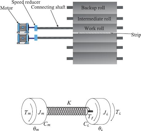
The rolling mill main drive system consists of motor,
speed reducer, connecting shaft and roll (Fig. 1). In the
main drive system, the mass of the motor, speed reducer,
and roll is large and the elasticity is small, while the con-
necting shaft has large elasticity and small mass. There-
fore, the system is simplified as a mass spring damping
system composed of inertia elements without stiffness and
elastic elements without mass, as shown in Fig. 2, where
T
m
is the motor torque, T
L
is the load torque, T
f
is the fric-
tion torque, J
m
,J
L
is the moment of inertia of motor and
load, C
m
,C
L
is the damping coefficient of motor and load,
θ
m
is the rotation angle of motor, θ
L
is the rotation angle of
roll, K is the stiffness coefficient of the connecting shaft.
According to Lagrange’s equation, the dynamic equa-
tion of the main drive system of rolling mill can be written
as
(
J
m
¨
θ
m
+C
m
˙
θ
m
+ K (θ
m
−θ
L
) = T
m
,
J
L
¨
θ
L
+C
L
˙
θ
L
+ K (θ
L
−θ
m
) = T
L
+ T
f
.
(1)
During the rolling process, products with different
thicknesses and specifications will cause uncertain distur-
bances to the load torque. Therefore, we can express the
load torque as follows:
T
L
= T
L1
+ T
LD
, (2)
Fig. 1. Structure composition diagram of the rolling mill
main drive system.
Fig. 2. Schematic diagram of the main drive system.

Adaptive Torsional Vibration Control of the Nonlinear Rolling Mill Main Drive System with Performance ... 3
where T
L1
is the load torque of steady rolling; T
LD
is the
disturbance of load torque during rolling with different
specifications and T
LD
is bounded, thus T
L
≤
¯
T
L
.
The friction torque of roll can be expressed as follows:
T
f
= µPR, (3)
where µ is the friction coefficient between strip and roll,
P is rolling force, R is work roll radius. The friction coef-
ficient at the roll gap during rolling can be expressed as
µ = ae
−bv
L
+c
, (4)
where a,b,c are variable parameters and v
L
is roll rotation
linear speed and v
L
=
˙
θ
L
Rwith
˙
θ
L
is roll angular velocity.
Take (3)-(4) into (1) and expand the friction coefficient
according to Taylor’s formula, it can be obtained
J
m
¨
θ
m
+C
m
˙
θ
m
+ K (θ
m
−θ
L
) = T
m
,
J
L
¨
θ
L
+C
L
˙
θ
L
+ K (θ
L
−θ
m
)
= T
L
+ aRPe
c
−aRPe
c
bR
˙
θ
L
−
1
2
b
2
R
2
˙
θ
2
L
.
(5)
2.2. Problem formulation
By defining x
1
=
˙
θ
L
,x
2
= θ
m
−θ
L
,x
3
=
˙
θ
m
, we can ob-
tain that
˙x
1
=
K
J
L
x
2
+
T
L
J
L
+
aPRe
c
(1 −bRx
1
+
b
2
R
2
2
x
2
1
) −C
L
x
1
J
L
,
˙x
2
= x
3
−x
1
,
˙x
3
=
T
m
J
m
−
C
m
J
m
x
3
−
K
J
m
x
2
.
(6)
In this paper, the actual measurement values of states
are obtained by sensors with sensor errors, which are mod-
eled as follows:
ˇx
i
= λ
i
x
i
, (7)
where λ
i
6= 0(i = 1,2,3) are unknown constants. Without
loss of generality, we assume the unknown measurement
sensitivities λ
i
> 0.
When torsional vibration occurs in the system, the load
speed will be unstable. If we design an appropriate motor
torque to make the load speed stable at a constant value,
then we can effectively suppress the occurrence of tor-
sional vibration. Although there is a sensor error between
the measured load speed and the actual speed, if we can
stabilize the measured load speed at a stable value, the
torsional vibration phenomenon can also be suppressed.
The objective of this paper is to construct robust adaptive
controller T
m
such that:
O1: The measured load speed can be stabilized at a con-
stant value with performance constraints.
O2: All the state variables of the closed-loop system are
bounded.
Remark 1: For the rolling mill main drive system is
free of sensor errors, [22–26] investigated the torsional vi-
bration suppression control strategy without performance
constraints. However, in practice, there are always perfor-
mance constraint requirements for the load speed of the
main drive system, moreover, the measurement signals of-
ten have sensor errors. In this paper, we design the robust
adaptive control strategy for the main drive system with
unknown states sensor errors. The control strategy pro-
posed in this paper takes into account more practical con-
ditions, and based on the idea of performance constraints,
the performance of the load speed is limited to a predeter-
mined range.
3. MOTOR TORQUE DESIGN
In this section, we will propose the adaptive state feed-
back controller design for system (6) with sensor errors
and performance constraints. The performance constraints
transformation of load speed is proposed at first, and then
the memoryless adaptive state controller is designed.
3.1. Performance constraints transformation
In order to suppress torsional vibration, we define ˇz
1
=
ˇx
1
−x
d
, where x
d
is a constant that represents the steady
state load speed. Then from (6) and (7), the dynamic of ˇz
1
is that
.
ˇz
1
=λ
1
K
J
L
x
2
+
T
L
J
L
+
aPRe
c
(1−bRx
1
+
b
2
R
2
2
x
2
1
)−C
L
x
1
J
L
!
.
(8)
The transient and steady-state performances of ˇz
1
is pre-
served if the following inequality holds
−δ µ (t) < ˇz
1
<
¯
δ µ (t), (9)
where δ and
¯
δ are the chosen positive constants, µ (t) =
(µ (0)−µ (∞))e
−kt
+ µ (∞) with µ (0) > 0, µ (∞) > 0,k >
0.
We set ˇz
1
= µ (t) S (ε) and S (ε) =
¯
δ e
ε
−δ e
−ε
e
ε
+e
−ε
. Since the
function S(ε) is strictly monotonic increasing, its inverse
function exists as
ε = S
−1
ˇz
1
µ (t)
=
1
2
ln
s + δ
¯
δ −s
. (10)
For the controller design of the main drive system of
rolling mill, we design the following state transformation
z
1
= ε −
1
2
ln
δ
¯
δ
, (11)
and then the transformation state dynamic is
˙z
1
=
rλ
1
K
J
L
x
2
+
rλ
1
T
L
J
L
−r
ˇz
1
˙
µ (t)
µ (t)
,

4 Cheng Qian, Liuliu Zhang, and Changchun Hua
+ rλ
1
aPRe
c
(1 −bRx
1
+
b
2
R
2
2
x
2
1
) −C
L
x
1
J
L
, (12)
where r =
1
2µ
h
1
s+δ
−
1
s−
¯
δ
i
. Then if z
1
is proved to be
bounded, the performance constraints of the load speed
is guaranteed.
3.2. Motor torque design procedure
In this section, we will use the adaptive approxima-
tion method to deal with the unknown sensor errors.
With respect to the unknown parameters, define Θ =
max
n
λ
2
1
λ
2
2
,
1
λ
1
,λ
1
,
1
λ
2
1
,λ
2
1
,
λ
2
2
λ
2
3
,
λ
2
λ
1
,
λ
3
λ
2
o
, ρ
1
=
λ
2
λ
1
,ρ
2
=
λ
3
λ
2
,ρ
3
=
1
λ
3
. Let
ˆ
Θ and
ˆ
ρ
i
be the estimations of Θ and ρ
i
, respec-
tively, and the corresponding estimation errors are defined
as
˜
Θ = Θ−
ˆ
Θ and
˜
ρ
i
= ρ
i
−
ˆ
ρ
i
. The following lemmas play
very important role in the control design process.
Lemma 1 [37]: For any constant ε > 0 and any variable
z, the following relationship holds:
0 ≤
|
z
|
−
z
2
√
z
2
+ ε
2
≤ ε. (13)
Lemma 2 (Young’s inequality): For ∀(x,y) ∈ ℜ
2
, the
following inequality holds:
xy ≤
ε
p
p
|
x
|
p
+
1
qε
q
|
y
|
q
, (14)
where ε > 0, p > 1, q > 1 and (p −1) (q −1) = 1.
By using the dynamic surface control technique and
backstepping method, the design procedure for the main
drive system (6) consists of 3 steps, with the mo-
tor torque T
m
being deduced at the last step. First,
we introduce the following coordinate transformation
z
i+1
= ˇx
i+1
− v
i
, W
i+1
= v
i
− α
i
, where i = 1,2, α
i
and v
i
are the virtual controller and the filtered vir-
tual controller. Then, we define the compact sets Ω
i
=
n
∑
i
k=1
1
2
z
2
k
+
1
2
˜
Θ
2
+
∑
i−1
k=1
1
2
W
2
(k+1)
+
1
2
λ
1
λ
2
˜
ρ
2
1
≤ 2µ
o
, where
µ > 0 is a constant.
Step 1: To stabilize the first error transformation z
1
, the
first virtual controller α
1
and the adaptive law
.
ˆ
ρ
1
are pre-
sented as
α
1
= −
J
L
z
1
r
ˆ
ρ
2
1
¯
α
2
1
K
p
z
2
1
r
2
ˆ
ρ
2
1
¯
α
2
1
+ ε
2
12
, (15)
.
ˆ
ρ
1
= z
1
r
¯
α
1
−l
1
ˆ
ρ
1
, (16)
with
¯
α
1
is designed in (27), l
i
(i = 1,2,3) and ε
i j
(i =
1,2, 3, j = 1, 2) are designed positive parameters. Then,
in order to obtain the filter virtual control v
1
, let α
1
pass
through a first-order filter with constant τ
1
, we obtain
τ
1
˙v
1
+ v
1
= α
1
,α
1
(0) = v
1
(0). (17)
The dynamic of the boundary layer error W
2
is
˙
W
2
= −
W
2
τ
1
+ B
1
, (18)
where B
1
is the continuous function, which are obtained
based on the derivation of α
1
. Moreover, B
1
has maximum
¯
B
1
on the compact set Ω
1
.
Considering the first Lyapunov function
V
1
=
1
2
z
2
1
+
1
2
˜
Θ
2
+
1
2
λ
1
λ
2
˜
ρ
2
1
+
1
2
W
2
2
, (19)
the derivative of V
1
is
˙
V
1
=z
1
˙z
1
−
˜
Θ
.
ˆ
Θ −
λ
1
λ
2
˜
ρ
1
.
ˆ
ρ
1
+W
2
˙
W
2
=z
1
rλ
1
K
J
L
x
2
+
rλ
1
T
L
J
L
+ r
ˇz
1
˙
µ (t)
µ (t)
−z
1
rλ
1
aPRe
c
(1 −bRx
1
+
b
2
R
2
2
x
2
1
) −C
L
x
1
J
L
−
˜
Θ
.
ˆ
Θ −
λ
1
λ
2
˜
ρ
1
.
ˆ
ρ
1
+W
2
−
W
2
τ
1
+ B
1
=z
1
rλ
1
K
J
L
λ
2
(z
2
+ α
1
+W
2
) + z
1
rλ
1
T
L
J
L
−z
1
r
abe
c
PR
2
−C
L
J
L
ˇx
1
−z
1
r
ˇz
1
˙
µ (t)
µ (t)
−
˜
Θ
.
ˆ
Θ
+ z
1
r
aPRe
c
(λ
1
+
b
2
R
2
2
1
λ
2
1
ˇx
3
1
)
J
L
−
λ
1
λ
2
˜
ρ
1
.
ˆ
ρ
1
+W
2
−
W
2
τ
1
+ B
1
. (20)
By using Lemma 2, one has
z
1
r
Kλ
1
J
L
λ
2
(z
2
+W
2
) ≤a
11
K
J
L
2
Θz
2
1
r
2
+
1
2a
11
z
2
2
+
1
2a
11
W
2
2
, (21)
z
1
rλ
1
T
L
J
L
≤
a
12
2
¯
T
L
J
L
2
Θz
2
1
r
2
+
1
2a
12
, (22)
z
1
r
aPRe
c
(λ
1
+
b
2
R
2
2
1
λ
2
1
ˇx
3
1
)
J
L
≤
|
z
1
r
|
aPRe
c
J
L
(1 +
b
2
R
2
2
ˇx
3
1
)Θ
≤ ε
11
Θ +
z
2
1
r
2
aPRe
c
J
L
(1 +
b
2
R
2
2
ˇx
3
1
)
2
r
z
2
1
r
2
aPRe
c
J
L
(1 +
b
2
R
2
2
ˇx
3
1
)
2
+ ε
2
11
Θ,
(23)
W
2
B
1
≤
a
13
2
¯
B
2
1
W
2
2
+
1
2a
13
, (24)
where a
i j
(i, j = 1, 2,3) are designed positive parameters.
With Lemma 1 and (15), we can obtain
z
1
r
Kλ
1
J
L
λ
2
α
1
= −
z
2
1
r
2
ˆ
ρ
2
1
¯
α
2
1
p
z
2
1
r
2
ˆ
ρ
2
1
¯
α
2
1
+ ε
2
12
λ
1
λ
2

Adaptive Torsional Vibration Control of the Nonlinear Rolling Mill Main Drive System with Performance ... 5
≤ ε
12
λ
1
λ
2
−z
1
r
ˆ
ρ
1
¯
α
1
λ
1
λ
2
. (25)
Substituting (21)-(25) into (20) gives
˙
V
1
≤
1
2a
11
z
2
2
+ ε
11
Θ + ε
12
λ
1
λ
2
+
1
2a
12
+
1
2a
13
+ z
1
r
abe
c
PR
2
−C
L
J
L
ˇx
1
−z
1
r
ˇz
1
˙
µ (t)
µ (t)
−z
1
r
ˆ
ρ
1
¯
α
1
λ
1
λ
2
−z
1
r
˜
ρ
1
¯
α
1
λ
1
λ
2
+ l
1
λ
1
λ
2
ˆ
ρ
1
˜
ρ
1
+ z
1
rΘN
1
−
˜
Θ
.
ˆ
Θ +
−
1
τ
1
+
a
13
2
¯
B
2
1
+
1
2a
11
W
2
2
,
(26)
where N
1
= a
11
K
J
L
2
z
1
r +
z
1
r
aPRe
c
J
L
(1+
b
2
R
2
2
|
ˇx
3
1
|
)
2
r
z
2
1
r
2
aPRe
c
J
L
(1+
b
2
R
2
2
|
ˇx
3
1
|
)
2
+ε
2
11
+
a
12
2
¯
T
L
J
L
2
z
1
r.
From the definition of
˜
ρ
i
, −z
1
r
ˆ
ρ
1
¯
α
1
λ
1
λ
2
−z
1
r
˜
ρ
1
¯
α
1
λ
1
λ
2
=
−z
1
rρ
1
¯
α
1
λ
1
λ
2
= −z
1
r
¯
α
1
is satisfied. Then, choose
¯
α
1
=
ˆ
ΘN
1
−
ˇz
1
˙
µ (t)
µ (t)
+
abe
c
PR
2
−C
L
J
L
ˇx
1
+
h
1
z
1
r
, (27)
and with
l
1
λ
1
λ
2
ˆ
ρ
1
˜
ρ
1
≤ −
l
1
2
λ
1
λ
2
˜
ρ
2
1
+
l
1
2
λ
1
λ
2
ρ
2
1
, (28)
finally, we get
˙
V
1
≤−h
1
z
2
1
−τ
∗
1
W
2
2
−
l
1
2
λ
1
λ
2
˜
ρ
2
1
+
1
2a
11
z
2
2
+ O
1
−
˜
Θ
.
ˆ
Θ + τ
0
ˆ
Θ −z
1
rN
1
+ τ
0
˜
Θ
ˆ
Θ, (29)
where τ
0
is a positive designed constant, τ
∗
1
=
1
τ
1
−
a
13
2
¯
B
2
1
−
1
2a
11
, O
1
= ε
11
Θ + ε
12
λ
1
λ
2
+
1
2a
12
+
1
2a
13
+
l
1
2
λ
1
λ
2
ρ
2
1
.
Step 2: The second transformation for the main drive
system z
2
= ˇx
2
−v
1
will be considered. The derivative of
z
2
along (6) and (7) is that
˙z
2
=
λ
2
λ
3
ˇx
3
−
λ
2
λ
1
ˇx
1
− ˙v
1
. (30)
The second virtual control law α
2
and the adaptive law
.
ˆ
ρ
2
are proposed as
α
2
= −
z
2
ˆ
ρ
2
2
¯
α
2
2
p
z
2
2
ˆ
ρ
2
2
¯
α
2
2
+ ε
2
22
, (31)
.
ˆ
ρ
2
= z
2
¯
α
2
−l
2
ˆ
ρ
2
, (32)
where
¯
α
2
is designed later. Similarly, let α
2
pass through
a first-order filter v
2
with constant τ
2
to obtain v
2
,
τ
2
˙v
2
+ v
2
= α
2
, α
2
(0) = v
2
(0), (33)
and then the dynamic of the boundary layer error W
3
is
˙
W
3
= −
W
3
τ
2
+ B
2
, (34)
where B
2
has maximum
¯
B
2
on the compact set Ω
2
.
Similar to Step 1, we choose the second Lyapunov func-
tion as
V
2
= V
1
+
1
2
z
2
2
+
1
2
λ
2
λ
3
˜
ρ
2
2
+
1
2
W
2
3
, (35)
and take the time derivative of V
2
along (30) and (35)
yields
˙
V
2
≤−h
1
z
2
1
−τ
∗
1
W
2
2
−
l
1
2
λ
1
λ
2
˜
ρ
2
1
+
1
2a
11
z
2
2
+ O
1
−
˜
Θ
.
ˆ
Θ + τ
0
ˆ
Θ −z
1
rN
1
+ τ
0
˜
Θ
ˆ
Θ −
λ
2
λ
3
˜
ρ
2
.
ˆ
ρ
2
+ z
2
λ
2
λ
3
(z
3
+ α
2
+W
3
) −
λ
2
λ
1
ˇx
1
− ˙v
1
+W
3
˙
W
3
.
(36)
With Lemma 1 and Lemma 2, the following inequalities
hold,
z
2
λ
2
λ
3
(z
3
+W
3
) ≤ a
21
Θz
2
2
+
1
2a
21
z
2
3
+
1
2a
21
W
2
3
, (37)
−z
2
λ
2
λ
1
ˇx
1
≤ ε
21
Θ +
z
2
2
ˇx
2
1
p
z
2
2
ˇx
2
1
+ ε
2
21
Θ, (38)
λ
2
λ
3
z
2
α
2
= −
z
2
2
ˆ
ρ
2
2
¯
α
2
2
p
z
2
2
ˆ
ρ
2
2
¯
α
2
2
+ ε
2
22
λ
2
λ
3
≤ ε
22
λ
2
λ
3
−z
2
ˆ
ρ
2
¯
α
2
λ
2
λ
3
, (39)
W
3
B
2
≤
a
22
2
¯
B
2
2
W
2
3
+
1
2a
22
, (40)
l
2
λ
2
λ
3
ˆ
ρ
2
˜
ρ
2
≤ −
l
2
2
λ
2
λ
3
˜
ρ
2
2
+
l
2
2
λ
2
λ
3
ρ
2
2
. (41)
By choosing
¯
α
2
= h
2
z
2
− ˙v
1
+ N
2
ˆ
Θ +
1
2a
11
z
2
with N
2
=
a
21
z
2
+
z
2
ˇx
2
1
√
z
2
2
ˇx
2
1
+ε
2
21
, one can obtain
˙
V
2
≤
1
2a
21
z
2
3
−h
1
z
2
1
−h
2
z
2
2
−
l
1
2
λ
1
λ
2
˜
ρ
2
1
−
l
2
2
λ
2
λ
3
˜
ρ
2
2
−τ
∗
1
W
2
2
−τ
∗
2
W
2
3
−
˜
Θ
.
ˆ
Θ + τ
0
ˆ
Θ −z
1
rN
1
−z
2
N
2
+ τ
0
˜
Θ
ˆ
Θ + O
2
, (42)
where τ
∗
2
=
1
τ
2
−
a
22
2
¯
B
2
2
−
1
2a
21
, O
2
= O
1
+ ε
21
Θ + ε
22
λ
2
λ
3
+
l
2
2
λ
2
λ
3
ρ
2
2
+
1
2a
22
.
Step 3: Consider the third error transformation as z
3
=
ˇx
3
−v
2
, then, the derivative of z
3
is that
˙z
3
=
λ
3
T
m
J
m
−
C
m
J
m
ˇx
3
−
K
J
m
λ
3
λ
2
ˇx
2
− ˙v
2
(43)

6 Cheng Qian, Liuliu Zhang, and Changchun Hua
The motor torque T
m
and the adaptive laws
.
ˆ
ρ
3
,
.
ˆ
Θ are de-
signed as
T
m
= −
J
m
z
3
ˆ
ρ
2
3
¯
α
2
3
p
z
2
3
ˆ
ρ
2
3
¯
α
2
3
+ ε
2
32
(44)
.
ˆ
ρ
3
= z
3
¯
α
3
−l
3
ˆ
ρ
3
(45)
.
ˆ
Θ = −τ
0
ˆ
Θ + z
1
rN
1
+ z
2
N
2
+ z
3
N
3
(46)
with N
3
=
K
2
J
2
m
z
3
ˇx
2
2
r
K
2
J
2
m
z
2
3
ˇx
2
2
+ε
2
31
and
¯
α
3
=
1
2a
21
z
3
−
C
m
J
m
ˇx
3
− ˙v
2
+N
3
ˆ
Θ+
h
3
z
3
.
Choose the whole Lyapunov function as
V
3
= V
2
+
1
2
z
2
3
+
1
2
λ
3
˜
ρ
2
3
. (47)
The time derivative of V
3
can be derived as
˙
V
3
≤
1
2a
21
z
2
3
−h
1
z
2
1
−h
2
z
2
2
−
l
1
2
λ
1
λ
2
˜
ρ
2
1
−
l
2
2
λ
2
λ
3
˜
ρ
2
2
−τ
∗
1
W
2
2
−τ
∗
2
W
2
3
−
˜
Θ
.
ˆ
Θ + τ
0
ˆ
Θ −z
1
rN
1
−z
2
N
2
+ z
3
λ
3
T
m
J
m
−
C
m
J
m
ˇx
3
−
K
J
m
λ
3
λ
2
ˇx
2
− ˙v
2
−λ
3
˜
ρ
3
.
ˆ
ρ
3
+ τ
0
˜
Θ
ˆ
Θ + O
2
. (48)
Considering the following inequalities also hold,
−z
3
K
J
m
λ
3
λ
2
ˇx
2
≤ ε
31
Θ +
K
2
J
2
m
z
2
3
ˇx
2
2
q
K
2
J
2
m
z
2
3
ˇx
2
2
+ ε
2
31
Θ, (49)
λ
3
T
m
z
3
J
m
≤ ε
32
λ
3
−λ
3
z
3
ˆ
ρ
3
¯
α
3
, (50)
with
l
3
λ
3
ˆ
ρ
3
˜
ρ
3
≤ −
l
3
2
λ
3
˜
ρ
2
3
+
l
3
2
λ
3
ρ
2
3
, (51)
τ
0
˜
Θ
ˆ
Θ ≤ −
τ
0
2
˜
Θ
2
+
τ
0
2
Θ
2
, (52)
we have
˙
V
3
≤−h
1
z
2
1
−h
2
z
2
2
−h
3
z
2
3
−
l
1
2
λ
1
λ
2
˜
ρ
2
1
−
l
2
2
λ
2
λ
3
˜
ρ
2
2
−
l
3
2
λ
3
˜
ρ
2
3
−τ
∗
1
W
2
2
−τ
∗
2
W
2
3
−
τ
0
2
˜
Θ
2
+ O
3
≤−νV
3
+ O
3
, (53)
where O
3
= O
2
+
l
3
2
λ
3
ρ
2
3
+
τ
0
2
Θ
2
+ ε
31
Θ + ε
32
λ
3
, ν =
min{2h
1
, 2h
2
, 2h
3
, l
1
, l
2
, l
3
, 2τ
∗
1
, 2τ
∗
2
, τ
0
}.
Let ν > O
3
/µ, then
˙
V
3
< 0 on V
3
= µ. Thus, V
3
≤ µ is
an invariant set, that is, if V
3
(0) ≤ µ, then V
3
(t) ≤ µ for
all t > 0. Inequality (53) implies that V
3
(t) ≤V
3
(0)e
−νt
+
O
3
ν
(1 −e
−νt
). Then, we can obtain that as t → ∞,z
i
≤
q
2O
3
ν
,W
i
≤
q
2O
3
ν
. With the above analysis, we present
the main results of this paper as follows:
Theorem 1: Considering the main drive system of
rolling mill expressed by (1) with the unknown measure-
ment sensitivities, the dynamic controllers (15), (31) and
(44) with adaptive laws (16), (32), (45), (46) render the
load speed to a stable value with transient and steady-state
performance constraints and all signals in the main drive
system are semi-globally uniformly ultimately bounded.
Remark 2: From the definition of parameter O
3
follow-
ing (53), we can know that it contains many items. How-
ever, we add some adjustable parameters τ
0
, τ
1
, τ
2
, a
i j
,
l
i
, ε
i, j
and h
i
in the derivation of the Lyapunov function.
Here, parameters τ
1
, τ
2
and h
i
are all positive constants
and should be selected big enough, while parameters τ
0
,
l
i
, ε
i, j
and a
i, j
are positive constants and should be small
enough such that the residual set can be arbitrarily small
to obtain the better control performance. Moreover, we
consider the performance constraints control in this paper
and the load speed would be guaranteed into a designer-
specified region even with larger O
3
.
Remark 3: From (21)-(23), (25), (37)-(39), and (49)-
(50), we can observe that many unknown parameters are
located in different locations caused by unknown sensor
errors, which significantly enlarges the system under con-
sideration. In this paper, instead of directly estimating the
multiple unknown parameters, we estimate the bound of
them. Moreover, with the aid of dynamic surface tech-
niques, the control design procedure is simplified with
very few adaptive laws and the “explosion of complexity”
caused by backstepping technique can be avoided.
4. SIMULATION EXAMPLE
In order to verify the effectiveness of the algorithm pro-
posed in this paper, the No. 5 stand of the 2030 mm tan-
dem cold rolling mill was selected as the simulation ob-
ject, and the corresponding main drive system equipment
parameters are as follows: T
L
= 14500 N·m, J
m
= 1552
kg·m
2
, J
L
= 1542 kg·m
2
, K = 5.93 ×10
6
N·m/rad, C
m
=
2 × 10
5
N/(m/s), C
L
= 2 × 10
6
N/(m/s), P = 7807 kN,
R = 0.4 m, a = 0.13, b = 0.002, c = 0.2.
The performance constraints function is selected as
−5e
−5t
−0.5 < ˇz
1
< 2.5e
−5t
+ 0.5. The control laws and
the adaptive laws are selected as (15)-(16), (31)-(32), (44)-
(46) with x
d
= 20, a
i j
= 10 (i, j = 1, 2, 3), l
i
= 1 (i = 1,
2, 3), τ
0
= 1, τ
1
= τ
2
= 500, ε
i j
= 0.01 (i = 1, 2, 3, j = 1,
2), h
i
= 100 (i = 1, 2, 3). The sensor errors are chosen as
λ
1
= 0.8, λ
2
= 0.7, λ
3
= 0.9. The initial values are selected
as [x
1
, x
2
, x
3
,
ˆ
ρ
1
,
ˆ
ρ
2
,
ˆ
ρ
3
, v
1
, v
2
,
ˆ
Θ] = [25, 20, 20, 0, 0, 0, 0,
0, 0].
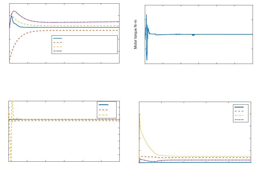
The simulation results are shown in Figs. 3-6. From
Fig. 3, we can see that the requirements of load speed
with performance constraints can be achieved. To validate
Adaptive Torsional Vibration Control of the Nonlinear Rolling Mill Main Drive System with Performance ... 7
Time s
0 0.5 1 1.5 2 2.5 3
Error of measurement load speed m/s
-6
-4
-2
0
2
4
Error with performance constraint
Lower bound
Upper bound
Error without performance constraint
Fig. 3. Tracking error of measurement load speed and the
performance constraints.
Time s
0 0.5 1 1.5 2 2.5 3
-600
-500
-400
-300
-200
-100
0
100
200
300
x(1)
x(2)
x(3)
Fig. 4. The state responses of the main drive system.
the improved performance with the proposed schemes, the
tracking error of load speed under the control of conven-
tional backstepping algorithm without prescribed perfor-
mance in the same parameter selection is also plotted in
Fig. 3. It can be observed that the convergence speed,
steady-state error and overshoot can be further reduced
to the preset range with the proposed schemes, and then,
the transient-state and steady-state performances are en-
hanced. Fig. 4 shows the state variables of the closed-loop
system, from which we can see that they are all bounded.
The motor torque and the adaptive laws are shown in
Fig. 5 and Fig. 6.
5. CONCLUSION
This paper established the torsional vibration mathe-
matical model and studied the torsional vibration suppres-
sion control problem of the main drive system of rolling
mill. The unknown measurement sensitivities in state vari-
ables caused by sensors are considered. With the help of
the performance constraints control, main drive system
torsional vibration controller is designed via backstepping
method and dynamic surface technology. The simulation
results show its effective performance on torsional vibra-
tion suppression.
Time s
0 0.5 1 1.5 2 2.5 3
×10
7
-1
-0.5
0
0.5
1
Fig. 5. The motor torque response.
Time s
0 2 4 6 8 10
0
2
4
6
8
10
ρ
1
ρ
2
ρ
3
Θ
Fig. 6. The adaptive law of the main drive system.
REFERENCES
[1] J. L. Chen, Z. G. Wang, J. Pan, Y. Y. Zi, Y. Wang, B.
Q. Chen, H. L. Sun, J. Yuan, and Z. J. He, “Customized
maximal-overlap multiwavelet denoising with data-driven
group threshold for condition monitoring of rolling mill
drivetrain,” Mechanical Systems and Signal Processing,
vol. 68-69, pp. 44-67, February 2016.
[2] L. Liu, N. Shao, S. Y. Ding, and Y. M. Fang, “Command
filter-based backstepping control for the speed and ten-
sion system of the reversible cold strip rolling mill using
disturbance observers,” International Journal of Control
Automation and Systems, 2019. DOI:10.1007/s12555-018-
0697-2
[3] P. Belli, S. Bittanti, and A. de Marco, “On the origin
of torsional vibrations in hot rolling mills and a possible
remedy,” Journal of Dynamic Systems Measurement and
Control-Transactions of the ASME, vol. 126, no. 4, pp. 811-
823, December 2004.
[4] K. Fujita and T. Saito, “Unstable vibration of roller mills,”
Journal of Sound and Vibration, vol. 297, no. 1-2, pp. 329-
350, October 2006.
[5] S. Liu, X. Li, Y. Q. Li, and H. B. Li, “Stability and bifur-
cation for a coupled nonlinear relative rotation system with
multi-time delay feedbacks,” Nonlinear Dynamics, vol. 77,
no. 3, pp. 923-934, August 2014.
8 Cheng Qian, Liuliu Zhang, and Changchun Hua
[6] J. L. Sun, Y. Peng, H. M. Liu, and G. B. Jiang, “Vertical
vibration of moving strip in rolling process based on beam
theory,” Chinese Journal of Mechnical Engineering, vol.
22, no. 5, pp. 680-687, October 2009.
[7] A. Heidari, M. R. Forouzan, and M. R. Niroomand, “De-
velopment and evaluation of friction models for chatter
simulation in cold strip rolling,” International Journal of
Advanced Manufacturing Technology, vol. 96, no. 5-8, pp.
2055-2075, May 2018.
[8] M. Mosayebi, F. Zarrinkolah, and K. Farmanesh, “Calcu-
lation of stiffness parameters and vibration analysis of a
cold rolling mill stand,” International Journal of Advanced
Manufacturing Technology, vol. 91, no. 9-12, pp. 4359-
4369, August 2017.
[9] X. B. Fan, Y. Zang, Y. K. Sun, and P. A. Wang, “Impact
analysis of roller system stability for four-high mill hori-
zontal vibration,” Shock and Vibration, A.N. 5693584, pp.
1-10, 2016.
[10] Y. Kim, C. W. Kim, S. Lee, and H. Park, “Dynamic model-
ing and numerical analysis of a cold rolling mill,” Interna-
tional Journal of Precision Engineering and Manufactur-
ing, vol. 14, no. 3, pp. 407-413, March 2013.
[11] Q. Y. Wang, Z. Y. Jiang, J. W. Zhao, and M. Fang, “Multi-
factor coupling system characteristic of the dynamic roll
gap in the high-speed rolling mill during the unsteady lu-
brication process,” Tribology International, vol. 67, pp.
174-181, November 2013.
[12] X. Yang and C. N. Tong, “Coupling dynamic model and
control of chatter in cold rolling,” Journal of Dynamic Sys-
tems Measurement and Control-Transactions of the ASME,
vol. 134, no. 4, pp. 041001-1-8, July 2012.
[13] S. Liu, S. S. Zhao, B. Niu, J. X. Li, and H. B. Li, “Sta-
bility analysis of a nonlinear electromechanical coupling
transmission system with time delay feedback,” Nonlinear
Dynamics, vol. 86, no. 3, pp. 1863-1874, November 2016.
[14] L. Q. Zeng, Y. Zang, Z. Y. Gao, K. Liu, and X. C. Liu, “ Sta-
bility analysis of the rolling mill multiple-modal-coupling
vibration under nonlinear friction,” Journal of Vibroengi-
neering, vol. 17, no. 6, pp. 2824-2836, September 2015.
[15] H. Y. Zhao and K. F. Ehmann, “Stability analysis of chatter
in tandem rolling mills-part 1: Single-and multi-stand neg-
ative damping effect,” Journal of Manufacturing Science
and Engineering-Transactions of the ASME, vol. 135, no.
3, pp. 031001-1-7, June 2013.
[16] X. Lu, J. Sun, G. T. Li, Q. L. Wang, and D. H. Zhang,
“Dynamic analysis of vibration stability in tandem cold
rolling mill,” Journal of Materials Processing Technology,
vol. 272, pp. 47-57, October 2019.
[17] S. P. He, H. Y. Fang, M. G. Zhang, F. Liu, X. L. Luan, and
Z. D. Ding, “Online policy iterative-based H
∞
optimization
algorithm for a class of nonlinear systems,” Information
Science, vol. 495, pp. 1-13, August 2019.
[18] X. H. Chang and G. H. Yang, “New results on output feed-
back H
∞
control for linear discrete-time systems,” IEEE
Trans. Automatic Control, vol. 59, no. 5, pp. 1355-1359,
May 2014.
[19] X. H. Chang, C. Yang, and J. Xiong, “Quantized fuzzy
output feedback H
∞
control for nonlinear system with ad-
justment of dynamic parameters,” IEEE Trans. on Systems,
Man, and Cybernetics: Systems, vol. 49, no. 10, pp. 2005-
2015, October 2019.
[20] S. P. He, H. Y. Fang, M. G. Zhang, F. Liu, and Z. D. Ding,
“Adaptive optimal control for a class of nonlinear systems:
the online policy iteration appraoch,” IEEE Trans. on Neu-
ral Networks and Learning Systems, vol. 31, no. 2, pp. 549-
558, February 2020.
[21] L. Ma, X. Huo, X. D. Zhao, and G. D. Zong, “Adaptive
fuzzy tracking control for a class of uncertain switched
nonlinear systems with multiple constraints: a small gain
approach,” International Journal of Fuzzy Systems, vol. 21,
no. 8, pp. 2609-2624, November 2019.
[22] X. Yang, K. X. Peng, and C. N. Tong, “Robust backstep-
ping control for cold rolling main drive system with non-
linear uncertainties,” Abstract and Applied Analysis, A.N.
387890, pp. 1-7, 2013.
[23] R. C. Zhang and C. N. Tong, “Torsional vibration control
of the main drive system of a rolling mill based on an ex-
tended state observer and linear quadratic control,” Jour-
nal of Vibration and Control, vol. 12, no. 3, pp. 313-327,
March 2006.
[24] K. Fujikawa, Z. Q. Yang, H. Kobayashi, and T. Koga,
“Robust and fast speed control for torsional system based
on state-space method,” Proc. of the Inter. Conf. Indus-
trial Electronics, Control and Instrumentation, pp. 687-
692, 1991.
[25] Y. A. Amer, A. T. El-Sayed, and F. T. El-Bahrawy, “Tor-
sional vibration reduction for rolling mill’s main drive sys-
tem via negative velocity feedback under parametric ex-
citation,” Journal of Mechanical Science and Technology,
vol. 29, no. 4, pp. 1581-1589, April 2015.
[26] R. Dhaouadi, K. Kubo, and M. Tobise, “Two-degree-
of-freedom robust speed controller for high-performance
rolling mill drives,” IEEE Trans. Industry Applications,
vol. 29, no. 5, pp. 919-926, October 1993.
[27] C. P. Bechlioulis and G. A. Rovithakis, “Robust adap-
tive control of feedback linearizable MIMO nonlinear sys-
tems with prescribed performance,” IEEE Trans. Automatic
Control, vol. 53, no. 9, pp. 2090-2099, October 2008.
[28] C. C. Hua, L. L. Zhang, and X. P. Guan, “Decentralized
output feedback adaptive NN tracking control for time-
delay stochastic nonlinear systems with prescribed perfor-
mance,” IEEE Trans. Neural Networks and Learning Sys-
tems, vol. 26, no. 11, pp. 2749-2759, November 2015.
[29] R. Chang, Y. M. Fang, L. Liu, and K. S. Kang, “Pre-
scribed performance adaptive neural tracking control for
strict-feedback Markovian jump nonlinear systems with
time-varying delay,” International Journal of Control, Au-
tomation, and Systems, vol. 15, no. 3, pp. 1020-1031, June
2017.
[30] B. W. Chen and L. G. Tan, “Adaptive anti-saturation track-
ing control with prescribed performance for hypersonic ve-
hicle,” International Journal of Control, Automation, and
Systems, vol. 18, no. 2, pp. 394-404, February 2020.

Adaptive Torsional Vibration Control of the Nonlinear Rolling Mill Main Drive System with Performance ... 9
[31] Z. Y. Guan, Y. P. Ma, Z. W. Zheng, and N. Guo, “Prescribed
performance control for automatic carrier landing with dis-
turbance,” Nonlinear Dynamics, vol. 94, no. 2, pp. 1335-
1349, June 2018.
[32] S. I. Han and J. M. Lee, “Prescribed performance fuzzy
backstepping control for nonlinear large-scale systems,”
International Journal of Control, Automation, and Systems,
vol. 13, no. 6, pp. 1508-1520, September 2015.
[33] L. Ma, X. Huo, X. D. Zhao, and G. D. Zong,
“Observer-based adaptive neural tracking control for
output-constrained switched MIMO nonstrict-feedback
nonlinear systems with unknown dead zone,” Nonlinear
Dynamics, vol. 99, no. 2, pp. 1019-1036, January 2020.
[34] X. Zhang and W. Lin, “A K-filter-based adaptive control for
nonlinear systems with unknown parameters in state and
output equations,” Automatica, vol. 105, pp. 186-197, July
2019.
[35] S. Y. Oh and H. L. Choi, “A further result on global
stabilization of a class of nonlinear systems by output
feedback with unknown measurement sensitivity,” Interna-
tional Journal of Control, Automation, and Systems, vol.
17, no. 10, pp. 2500-2507, October 2019.
[36] Z. Y. Sun, C. Y. Liu, S. F. Su, and W. Sun, “Robust sta-
bilization of high-order nonlinear systems with unknown
sensitivities and applications in humanoid robot manipula-
tion,” IEEE Trans. Systems Man and Cybernetics: Systems,
2019. DOI:10.1109/TSMC.2019.2931768
[37] C. L. Wang and Y. Lin, “Decentralized adaptive tracking
control for a class of interconnected nonlinear time-varying
systems,” Automatica, vol. 54, pp. 16-24, April 2015.
Cheng Qian received his B.S. degree
in mechanical engineering from Yanshan
University, Qinhuangdao, China, in 2014.
He is currently working toward a Ph.D.
degree in electrical engineering from Yan-
shan University. His research interests are
in dynamic modeling, analysis and control
of rolling process.
Liuliu Zhang received her B.S. and Ph.D.
degree in electrical engineering from Yan-
shan University, Qinhuangdao, China, in
2012 and 2018, respectively. She is cur-
rently a Lecturer with Electrical Engineer-
ing, Yanshan University, China. Her re-
search interests include nonlinear control,
constraint control and adaptive control.
Changchun Hua received his Ph.D. de-
gree in electrical engineering from Yan-
shan University, Qinhuangdao, China, in
2005. He was a research Fellow in Na-
tional University of Singapore from 2006
to 2007. From 2007 to 2009, he worked
in Carleton University, Canada, funded by
Province of Ontario Ministry of Research
and Innovation Program. From 2009 to
2011, he worked in University of Duisburg-Essen, Germany,
funded by Alexander von Humboldt Foundation. Now he is a
full Professor in Yanshan University, China. He is the author
or coauthor of more than 110 papers in mathematical, technical
journals, and conferences. He has been involved in more than
10 projects supported by the National Natural Science Founda-
tion of China, the National Education Committee Foundation of
China, and other important foundations. His research interests
are in nonlinear control systems, control systems design over
network, teleoperation systems and intelligent control.
Publisher’s Note Springer Nature remains neutral with regard
to jurisdictional claims in published maps and institutional affil-
iations.
