
Journal of Micro-Bio Robotics
https://doi.org/10.1007/s12213-020-00137-0
RESEARCH PAPER
Teleoperation control scheme for magnetically actuated
microrobots with haptic guidance
Ehab Al Khatib
1
· Xiao Zhang
1
· Min Jun Kim
1
· Yildirim Hurmuzlu
1
Received: 1 April 2020 / Revised: 22 July 2020 / Accepted: 28 July 2020
© Springer-Verlag GmbH Germany, part of Springer Nature 2020
Abstract
An external magnetic field can be used in remotely controlling magnetic microrobots, making them promising candidates
for diverse biomedical applications, including cell manipulation and therapy. This paper presents a teleoperation scheme
to control magnetically actuated microrobots. The system was developed to allow human operators to control the motion
for magnetically actuated microrobots and feel their interactions with the environment. The potential applications of the
presented system will be in targeted drug delivery, micro-assembly, and biopsy procedures. A haptic interface constituted
the core of the teleoperation system. It was used to provide the operator with force feedback to control the microrobots. In
particular, virtual interaction forces were computed and transmitted to the human operators to guide them in performing path
following tasks. The operating field of the microrobots was haptically rendered to avoid contacts with obstacles. Finally,
a basic set of experimental trials were conducted, demonstrating that the average path tracking error was reduced by 67%
when haptic feedback was used.
Keywords Microrobot · Teleoperation · Haptic · Motion control · Magnetically actuated robot
1 Introduction
Microscale robots, especially untethered ones, have been
intensively investigated due to the many possible applica-
tions: micro-manipulation, micro-fabrication, drug delivery,
tissue manipulation, in situ sensing, cell therapy and in
vivo diagnostics [1]. For example, in biomedical applica-
tions, microrobots can act as co-robots that directly work
on human patients, alongside healthcare providers, perform-
ing critical medical procedures. Such ideas have deep roots
in popular culture and may even be considered the final
frontier of medical microrobotics [2]. While most of the
This work was funded by the National Science Foundation (CMMI
1623324)
Electronic supplementary material The online version of
this article (https://doi.org/10.1007/s12213-020-00137-0) contains
supplementary material, which is available to authorized users.
Yildirim Hurmuzlu
1
Department of Mechanical Engineering, Southern Methodist
University, Dallas, TX 75275, USA
microrobots presented here are based on autonomous tech-
niques [1, 3–5], there is increasing importance in human-
in-the-loop strategies. For safety, public acceptance, and
responsibility [6], it is helpful to equip human operators
with efficient and intuitive ways for manipulating the micro-
robots. One such way is haptic feedback, making it an
important approach in these human-in-the-loop teleopera-
tion schemes [7 , 8].
Thus far, several haptic feedback devices have been
developed to control and manipulate microrobots. Bhatti
et al. [9] designed an intuitive haptic interface for Atomic
Force Microscopy (AFM), which estimates haptic force at
the end of the tip by using geometric deformation prin-
ciples. Another technique for haptic feedback is visual
sensing. Pacchierotti et al. [10] presents a particle-filter
based algorithm to track the position of a robot wirelessly
while a 6-DOF haptic interface enables the operator to
remotely move a microrobot to its target position. Boukhni
fer and Ferreira [11] used a 1-DOF haptic feedback to
employ a passivity-based approach with bilateral and robust
fault tolerant control. Mohand Ousaid et al. [12] investi-
gated a modular microteleportation system that includes
custom components designed to take into account passiv-
ity and transparency constraints. Mehdi Ammi and Antoine
Ferreira [13] use 3-D vision with haptic rendering for

J Micro-Bio Robot
manipulation and penetration of cells. Asgari et al. [14]
offer a method to represent the mechanical properties of
biological cells by considering a hybrid model of micro-
nano multi particles and continuum approaches. Abou Seif
et al. [15] present a telemanipulation system for param-
agnetic microparticles. A disturbance observer was used
to estimate the forces at both the haptic interface and the
microrobot. Guix et al. [ 16] designed microrobots with
an onboard vision-based 2D micro-force sensor. But, the
limitation of such a robot is the size where the footprint
is 719 μm × 1144 μm, which is relatively large in the
micro-robotics scales. While effective, these p reliminary
systems have no mechanism to estimate the ambient forces
acting on micro-robots when they encounter an unknown
fluid or obstacle. For this purpose, we propose the devel-
opment of a master-slave system for force feedback and
manipulation of micro/nano objects where force estimation
is not needed.
The magnetic tweezer system has six magnetic poles for
releasing magnetic field fluxes to generate magnetic field
gradients. By applying current to certain electromagnetic
coils on the poles, different magnetic gradient fields can
interact with magnetized microrobots to produce propulsion
magnetic forces [17–22]. The magnetic tweezer system
requires microrobots to be magnetic only without imposing
any restrictions on the structure or the rigidity [23].
Therefore, it can only affect magnetized objects, offering
advantages for in-vivo environments, as the biological
substances are mostly non-magnetized [23, 24]. In our
previous work, this magnetic tweezer system has achieved
closed-loop control for real time 3D manipulation and
swarm motion [5, 25], with inputs given through a
user customized control interface. However, to develop
the system further for human-in-the-loop application,
alternative methods to apply control inputs are necessary.
In this paper, we integrate a haptic device together with
the magnetic tweezer system to achieve path planning of
microrobots with the implementation of an artificial poten-
tial field in conjunction with a virtual grid map. We focus
on the teleoperation control of the magnetically actuated
microrobots and haptic rendering of the environment.
There are very few studies that incorporate haptic feed-
back with magnetic actuation in controlling microrobots.
The related work can be found in [10]. The difference is,
their robots utilize micro-jets powered by catalysis, and
magnetic field is used only for steering. Fabrication of the
robots in [10] requires elaborate chemical processes to build
robots that generate micro jets. In addition, haptic-feedback
provided to the user in the form of on/off vibrations when
a contact with a wall is detected using imaging data. Hap-
tic feedback is also used to feel the inertia of the robots to
facilitate steering. This approach relies on visual data for
operational as well as position feedback purposes.
The main contribution of the present paper is in the
way the force is computed as well as how it is rendered
to the user (what is called “interaction technique” in the
VR and Haptics fields.) The robots presented here are
simple ferro-magnetic beads, because there is no need for
on-board actuation. We use two artificial potential fields
one to render the environment and another for trajectory
tracking. The haptic feedback for external interaction is
not an on/off process. It is rather a proportional force
that provides the user with more realistic sensing of the
environment. For example, in our case, the user knows that
an obstacle is being approached and can avoid collision
altogether. Furthermore, we can render attractive potential
fields to facilitate more effective trajectory tracking. In our
method visual data is needed for position feedback only. If
an alternative method to acquire the position of the robots
can be used (such as ultrasound or magnetic sensing fields),
our approach does not need visual data altogether.
The rest of this paper is organized as follows. System
setup and the introduction of master and slave subsystems
are shown in Section 2. Section 3 illustrates the control
scheme for teleoperation. The mechanisms of the potential
field and haptic controller are discussed in Section 4.
Section 5 elaborates the experiment analysis, and the
conclusion is in Section 6.
2 Overview of the system
The experimental setup used for microrobot teleoperation is
shown in Fig. 1. The master device is a Novint Falcon haptic
device, while the slave system is the magnetic tweezer with
a magnetically actuated microrobot. The control algorithm
and communications software infrastructure make use of
Robotic Operating System (ROS) libraries and Matlab.
This selection simplifies developing, debugging and testing
stages.
The teleoperation system considered in this paper is
showninFig.1. The human operator commands the micro-
robot slave by moving the haptic device. This motion is
translated into forces that will be applied by the magnetic
actuation system. Lastly, when the microrobot approaches
an obstacle, the virtual interaction forces are transmitted to
the Falcon haptic interface, rendering the terrain as force
feedback.
2.1 The master device
The Novint Falcon is a haptic device, which has a 3-
DOF grip connected via three parallel arms. It can also be
used as a 3-DOF position input and force feedback device
[26]. It was chosen because of its low cost, simplicity, and
suitability for the current project.
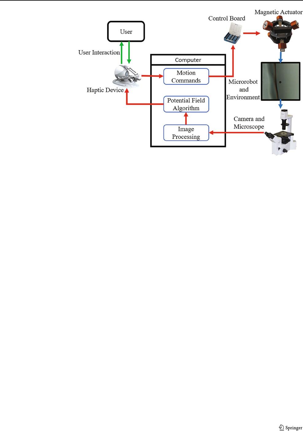
J Micro-Bio Robot
Fig. 1 Overview of the
teleoperation system: The
virtual interaction forces are
computed and transmitted to the
human operator to guide him in
performing path-following
tasks. The position of the haptic
device is used to compute the
motion commands sent to the
magnetic tweezer
The Falcon library translates cartesian pose state vector
to the ROS-based network using our customized software.
2.2 The slave station
The slave station consists of magnetically actuated micro-
robots, the magnetic tweezer [17], and a camera with a
microscope. The station will be connected to a computer for
visual feedback processing and implementation of motion
control. The microrobots are 10 μm coated ferromagnetic
particles.
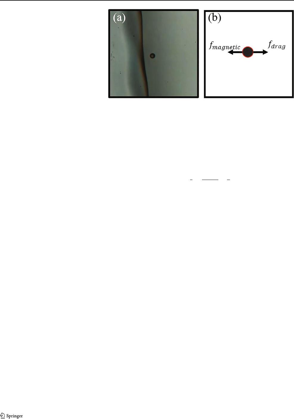
Magnetic particles are acted upon by forces that are
generated by an external magnetic field (B). In this study,
the magnetic force acting on a microrobot is given b y
f
magnetic
= (c.∇)B (1)
where, c is the magnetic moment of the magnetic particle
and ∇B is the magnetic field gradient. In Stokes flow, the
drag force on a microrobot undergoing translational motion
can be written as,
f
drag
=−ζ
P
x (2)
ζ = 6 πγr (3)
where,
P
x is the translational velocity of the microrobot in
x,y,z-directions with radius of r, γ is viscosity of the fluid,
and ζ is the spherical microrobot drag coefficient, which is
commonly known as Stokes’ law [27]. Figure 2 shows the
free-body diagram of the microrobot. Thus, the equation of
motion of the microrobot can be derived as follows:
m
¨
x − f
drag
= f
magnetic
(4)
where m is the mass of the microrobot.
3 Teleoperation control schemes
In this section, the three control strategies of teleoperation
are adopted from [28]aregivenas:
3.1 Position-position
The simplest and most intuitive teleoperation scheme is the
position-position control [29]). This control scheme maps
the master displacement to d esired slave displacement.
In order to overcome dimensional differences between
master/slave workspaces, a convenient scaling criteria or
a convenient clutching mechanism may be used. In our
application, however, this scheme requires closed-loop
position control on the slave side.
3.2 Position-velocity
When the slave workspace is significantly greater than
the one of the master, a scaling problem may arise.
One way of solving this issue is to map the master
device displacement to the slave desired velocity. This
mapping scheme provides more reliable performance and
is appropriate for teleoperation of microrobots with infinite
workspaces. Hence, similar to the position-position scheme,
it requires a velocity closed-loop control on the slave side.
3.3 Position-force
Similar to position-velocity scheme, the position-force
control scheme provides better performance when the slave
workspace is greater than the master’s. In this case, the
J Micro-Bio Robot
Fig. 2 a Microrobot in a static
fluid b The free-body diagram
of microrobot, which illustrates
the magnetic force and drag
force acting on the microrobot
forces applied to the slave are defined by the displacement
of the master. Therefore, the master displacement is
translated into magnetic force using
f
magnetic
= Kx
h
(5)
where, x
h
is the haptic device displacement and K is the
scaling matrix. To guarantee stability of the overall system,
a passivity-based approach has been adopted in the design
of the control scheme.
Assuming that the system is passive with respect to
the haptic tool, and if the interconnection between the
haptic tool and the microrobot cannot generate energy (i.e.
passive). Then, it can be concluded that the system is passive
and, therefore, stable. Thus, if the passivity is preserved by
Eq. 5, the overall system is guaranteed to be stable. From
Eqs. 4 and 5,ifx
h
is zero, then f
magnetic
is zero and the f
drag
will dissipate the energy. Then, it can be concluded that the
system is passive and stable.
4 Haptic guidance
The potential field algorithm we selected can be precom-
puted for the entire environment. Therefore, it will be
rapidly executed during runtime. It is a universal algorithm
that can be used for both path following guidance and ren-
dering obstacles imposed by the environment. Finally, it is
simple and can be used in a wide range of environments and
can handle higher degree of freedom tasks.
A virtual force can be generated by the environment and
the desired path to give the user a haptic feeling about the
workspace. This can be expressed as obstacle avoidance and
path following problem. Thus, we used artificial potential
fields to generate haptic forces to avoid obstacles and
follow a predefined path. The obstacles generate a repulsive
potential field, and the desired path generates an attractive
potential field. The two fields can be used separately to
perform each task and can be combined to perform the two
tasks in parallel.
4.1 Haptic rendering of the environment
Here, we used an artificial potential field to avoid obstacles.
First, a grid is generated and superimposed on the
environment. Then, each grid cell occupied by an obstacle
contributes a repulsive potential field as shown in Fig. 3.We
define C as a set of all occupied cells. The potential field U
i
is generated by a single cell c
i
∈ C as follows:
U
i
(x, x
c
i
) =
⎧
⎨
⎩
1
2
η
1
x−x
c
i
−
1
ρ
,
x − x
c
i
≤ ρ
0 , otherwise
(6)
where, x is the robot position, x
c
i
is the occupied cell
position, η is a positive scaling factor, and ρ is the range of
influence.
The resultant repulsive force is obtained from the
negative gradient of the repulsive potential. The repulsive
force exerted by each occupied cell is,
F
i
(x, x
c
i
) =−∇U
i
(x, x
c
i
) (7)
Using superposition, the total potential field U of all
occupied cells is:
U =
c
i
∈C
U
i
(x, x
c
i
) (8)
and the total repulsive force exerted by the environment on
the robot is given by:
F =−
c
i
∈C
∇U
i
(x, x
c
i
) (9)
Subsequently, the force F will be transmitted to the
Falcon haptic device in order to give the operator the
sensation that the microrobot is approaching an obstacle.
Figure 3 shows the obstacles and the boundaries, as well
as the generated artificial potential field. As can be seen,
each obstacle is surrounded by a potential field with a
specific area of influence. Therefore, once the microrobot
enters the field, the operator starts feeling the generated
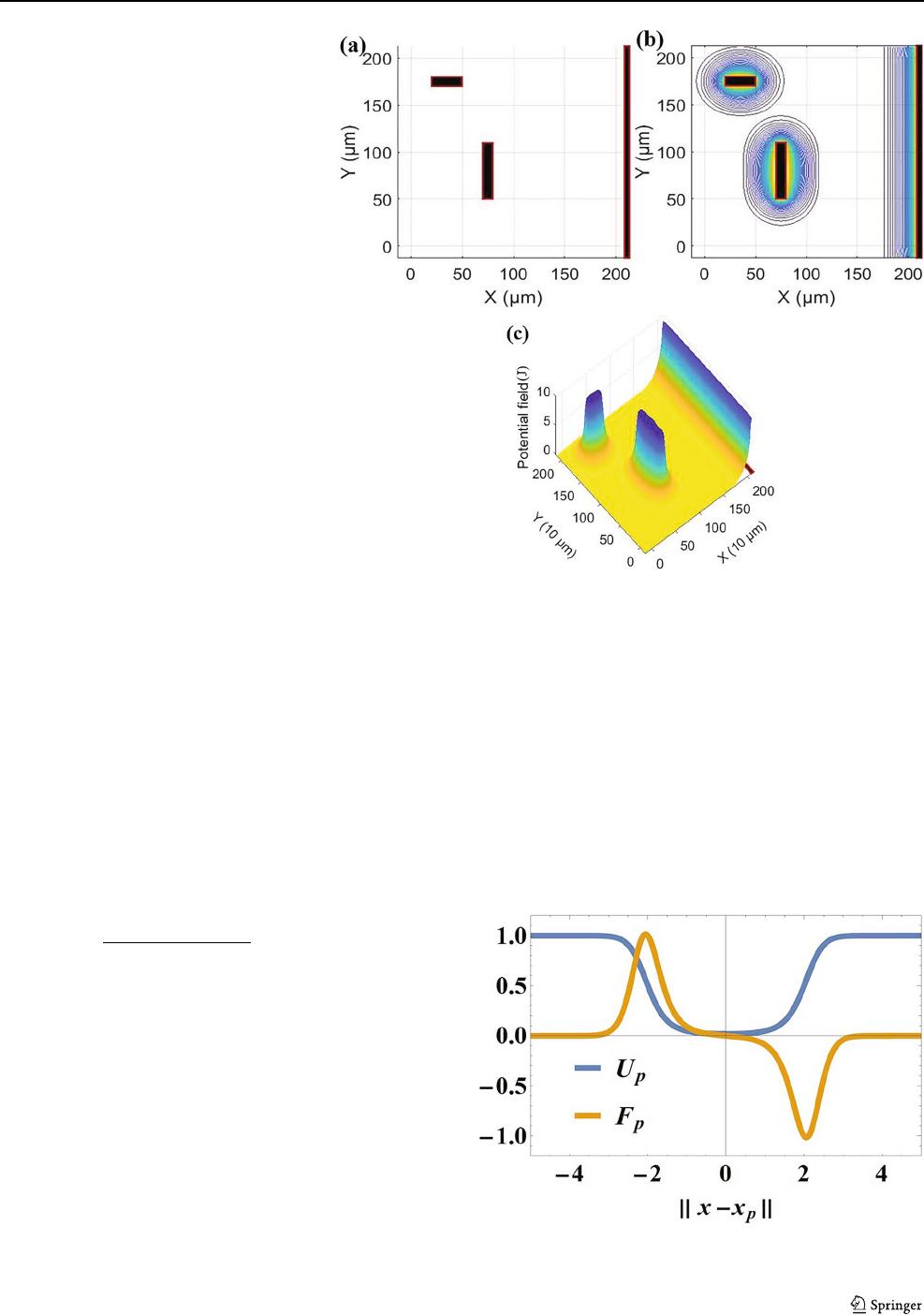
J Micro-Bio Robot
Fig. 3 Representation of the
environment. a Occupancy Grid
Mapping of the environment. b
Thegridmapwitharepulsive
potential field due to obstacles. c
3D presentation of the repulsive
field due to the obstacles
forces. As shown in Fig. 3c, the potential field gradient
around the obstacle position causes the forces to increase
proportionally as the microrobot gets closer to the obstacle.
4.2 Motion tracking
The haptic guidance problem can be addressed as a path
following problem. The goal is to minimize the distance
between a single microrobot and a predefined path. An
algorithm based on the artificial potential field is used
to generate a constrained motion in the proximity of the
desired path. The proposed attractive potential field U
p
is
expressed as:
U
p
(x, x
p
) =
1
1 + e
−(
x−x
p
2
−τ
2
)
(10)
where, x and x
p
are the microrobot and path point positions
respectively, and τ is the radius of attraction. The attractive
force can be easily derived as the negative gradient of the
field as given in
F
p
(x, x
p
) =−∇U
p
(x, x
p
) (11)
The potential field is constant, as the distance between
the robot and path is small, and therefore, its gradient van-
ishes. In addition, as the distance starts increasing the poten-
tial field increases, and its gradient changes and reaches its
maximum and minimum at τ and −τ respectively. As we
get further away from the desired path, the field becomes
constant again as shown in Fig. 4.
The artificial potential field around the desired path
serves as a guide for the operator. As the microrobot moves
along the path, the operator does not feel any force, but
when the operator drives the microrobot away from the
path, the operator feels forces indicating that the microrobot
is drifting. In this mode, the haptic feedback will guide
and influence but not constrain the operator to move the
microrobot along the desired path. The tracking accuracy
relies on visual feedback and the operator. This mode
combines visual and haptic feedback.
Fig. 4 The attractive field due to the path, when τ = 2
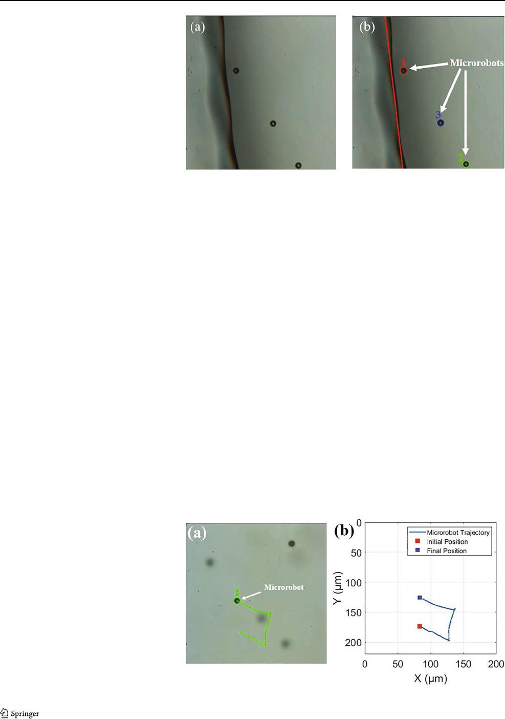
J Micro-Bio Robot
Fig. 5 Experimental results.a A
raw image of the video stream
depicting three microrobots and
an obstacle. b The detected
microrobots and the obstacle
using image processing
techniques
5 Experimental results
The experimental results section will be divided into four
parts: the first will discuss the experimental setup and
signal processing, the second will discuss the proposed
teleoperation scheme, where the haptic device will be used
to control the microrobot, the third will discuss the haptic
rendering of the environment, and the forth will discuss the
proposed teleoperation scheme with the haptic guidance to
track a desired path.
5.1 Experimental setup and signal processing
We used a magnetic tweezer system setup that was built
in house. The magnetic tweezer system was mounted
on an inverted microscope (Olympus IX50) with a 40X
microscope lens (Fig. 1). Each microrobot was made
from ferromagnetic microbeads (Spherotech SVFM-100-
4 Ferromagnetic Particle) with an average diameter of
10.6 μm. Subsequently, a population of microrobots, diluted
to 5% with 20% NaCl solution to minimize the aggregation
due to mutual magnetic attraction was also injected into
the PDMS (Polydimethylsiloxane) chamber. This chamber
was then placed in the center of the magnetic tweezer.
The purpose of 20% NaCl is to increase the density to
decrease particle sedimentation. Tween 20 was also added
to the solution in order to reduce the surface contact friction.
Tween 20 concentration is 10% and it is injected onto the
chamber surface before magnetic particle solution injection.
Volume ratio of magnetic particle solution and Tween 20
solution is 4:1 in the chamber.
The setup was designed such that the fluid was stationary,
so there would be no fluid flow in the inner chamber except
for the movement of microrobots. The control action was
restricted to a single bead of robots in the center o f the
chamber to avoid the drag forces due to the walls. Figure 5a
shows three microrobots and an obstacle. The positions
of the microrobots and the obstacle were estimated using
image processing techniques.
Image processing algorithms were used to estimate the
microrobot’s position from the video stream. We used a
circular Hough transform technique to detect the circles that
define the microrobots using phase coding [30]. The phase
coding is capable of estimating the center locations and radii
of the circles. We have added a filter tha limits the jumps
in position data to avoid sudden jumps in force feedback.
Additionally, the boundary can be modeled as a line for
visual and haptic rendering purposes. We extracted the line
Fig. 6 Experimental results. a A
10 μm microrobot is controlled
using the haptic interface. b The
microrobot trajectory, initial,
and final position are shown
J Micro-Bio Robot
Fig. 7 Experimental results. Particle velocities according to the
applied magnetic gradients
segments from the streamed images based on a Hough
transform [31] to detect an obstacle in the environment.
Figure 5b shows the three detected microrobots, which were
labeled as 1, 2, and 3. The red line represents the obstacle.
Finally, transmission delays are negligible because data
are exchanged over a local network and the robots move
with relatively slow velocities.
5.2 Teleoperation control
An experimental test was performed using the teleoperation
control scheme described in Section 3. A simple task was
conducted to evaluate the proposed teleoperation method.
The operator used the Falcon haptic interface as a joystick
to move the microrobots. As expressed in Eq. 5,the
displacement of the haptic device was converted to desired
magnetic forces to be generated at the slave station.
Figure 6a shows how the task was carried out, where the
microrobot was labeled as 2. The microrobot trajectory in
the x - y plane is shown in Fig. 6b, where the red square
Fig. 8 Experimental results. a
Position of the microrobot with
respect to the obstacle. b The
forces in x and y directions that
are obtained using the potential
field algorithm
Fig. 9 Experimental results.The haptic forces and the distance
between the microrobot and obstacle as a function of time
represents the initial position, and the blue square represents
the final position. Figure 7 shows the microrobot velocities
according the the applied magnetic gradients.
5.3 Haptic rendering of the environment
In this section, an experimental test was performed using
the teleoperation control scheme with haptic rendering of
the environment as described in Section 4. With awareness
of obstacle locations, a grid map of the environment was
constructed. Figure 8a shows a contour representation of the
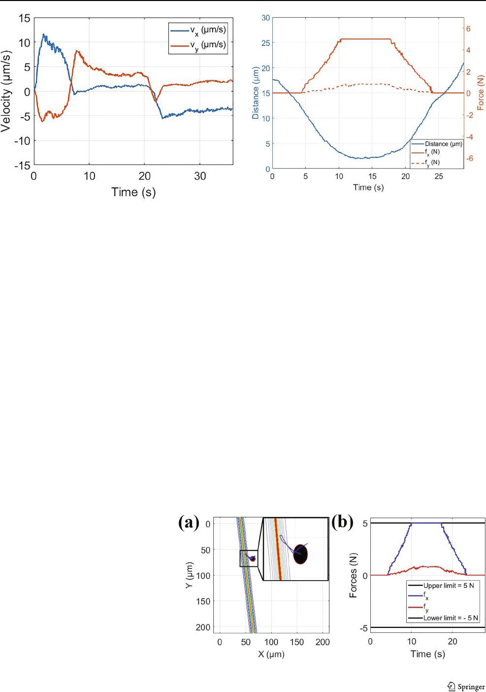
repulsive field due to an obstacle. Here, the influence range
of the obstacles is 10μm. Since we only have one haptic
interface, the operator can only feel the force acting on a
single robot. Thus, in this situation, microrobot (1) is the
microrobot of interest to be tracked and controlled by the
operator. Additionally, Fig. 8a shows the microrobot (1) and
its trajectory as the black circle and blue line, respectively.
The obstacle and its potential field are represented as a
red line with contour showing the area of influence of the
obstacle. As can be seen, the microrobot started from an
J Micro-Bio Robot
Fig. 10 Experimental results. a
A10μm microrobot is
controlled using the haptic
interface to follow a predefined
curved path. b The attractive
potential field around the path
initial location outside the influence region of the obstacle
potential field. As the operator move the microrobot in
the direction of the obstacle, the microrobot entered the
influence region, and the operator started to feel the forces
from the haptic device as shown in Fig. 8b. The blue
and red lines represent the forces in x and y directions,
respectively. The black lines represent the upper and lower
force limits of the Falcon haptic device. Also, as can be
seen from Fig. 8, the forces are proportional to the distance
between the microrobot and the obstacle. As the microrobot
approaches the obstacle, the operator felt stronger forces.
Finally, as the operator moved the microrobot away from
the obstacle, smaller forces were experienced until the
microrobot escaped the influence region of the obstacle.
Figure 9 indicates the haptic forces and the distance between
the microrobot and the obstacle as a function of time. The
blue line represents the distance, and the red and dashed red
represent the haptic forces in x and y directions.
5.4 Motion tracking
An experiment was carried out using the teleoperation
control scheme with the haptic guidance to track a desired
path. Five subjects took part in the experiment. In this
experiment, the microrobot locations are estimated using
the image processing techniques presented in Section 5.1.
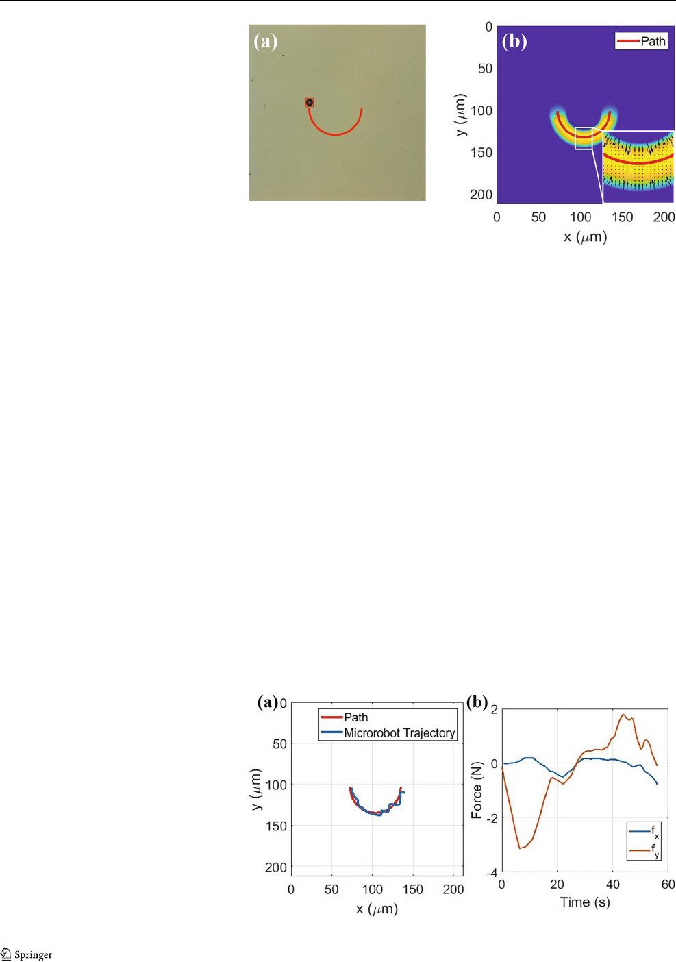
Figure 10a shows the microrobot as well as the desired
path. An attractive potential field was g enerated using the
algorithm discussed in Section 4.2. The field is shown in
Fig. 10b, where the predefined path is represented as a
red line encircled by the attractive potential field. In this
experiment, the operator attempted to follow the path in
the presence of haptic guidance, as shown in Fig. 11a.
Figure 11b shows the haptic forces felt by the operator.
As can be seen, when the microrobot drifted away from
the path, the haptic algorithm guided the operator back to
it. Figure 12 indicates the haptic forces and the distance
between the microrobot and the desired path as a function of
time. The blue line represents the distance, and the red and
dashed red represent the haptic forces in x and y directions.
6 Validation
For benchmarking purposes, two groups of experiments
were carried out. In the first group, we attempted to move
Fig. 11 Experimental results. a
A predefined curved path and a
10 μm microrobot trajectories. b
The haptic forces, which
displaced to operator
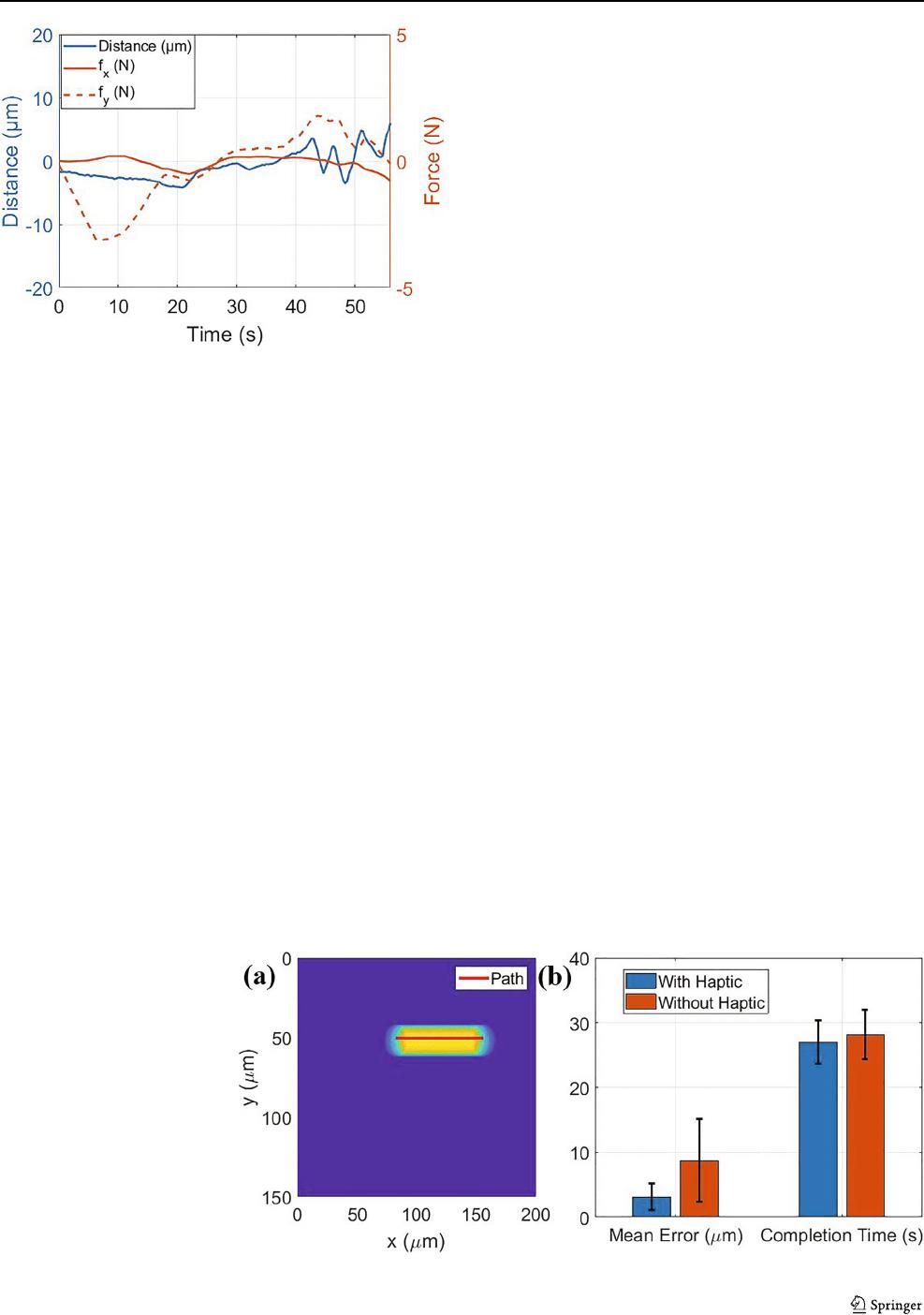
J Micro-Bio Robot
Fig. 12 Experimental results.The haptic forces and the distance
between the microrobot and desired path as a function of time
a single microrobot along a predefined path without haptic
guidance. Then, this task was repeated with haptic guidance.
At each trial, we were able to follow the displayed path with
minimal error. Two criteria were selected to evaluate the
benchmark process: average path error and completion time.
The average path error was calculated as the mean of the
perpendicular distance between the microrobot position and
the path. The completion time was the time period between
the time instants the operator started tracking the path and
when the end of path was reached. In this experiment, five
subjects took part. They are males with age range of 25 to 35
years, and two of them were familiar with haptic feedback.
Each individual repeated each task three times. Using haptic
is intuitive, and based on our experiments, we observed that
the subjects who were not familiar with haptics caught up with
the ones who were familiar with it after a single trial. After
that the results of both groups were very similar. Never-
theless, even during the first trial the performance of the
subjects who were not familiar with haptics was improved
compared to their performance without the haptic interface.
Fig. 13 Validation Test. a A
10 μm microrobot is controlled
using the haptic interface to
follow a predefined straight
path. b The results of the
validation study show that
teleoperation with haptics in the
loop is significantly better than
with visual feedback only
The data obtained from these experiments are seemingly
better when haptic feedback is used. As can be seen in
Fig. 13, the average path error was reduced by a factor of
three, accompanied by a slight decrease in the completion
time. The slight improvement of the completion time was
due to the simplicity of the task. Finally, a paired t-test was
conducted to check if adding haptic feedback would result
in statistically significant improvements. The p-values are
computed as 0.065 and 0.37 for mean error and completion
time, respectively. The paired t-test does not exhibits strong
statistical evidence of improvement. This is probably due to
the relatively lower number of trials.
7 Conclusion
We developed a teleoperation setup for microrobots using
a haptic device and magnetic tweezers. In our setup, the
microrobot is virtually linked to the haptic device. Its
movements are controlled by the movement of the haptic
tool. To improve task performance, the guidance forces
are presented to the operator through the haptic interface
for better task performance. We conducted a basic set of
trials where we tracked a straight line segment using the
Falcon device with and without haptic guidance. The trials
showed that haptic guidance significantly improves tracking
errors but leads to modest benefits in task completion
time. Future work will aim at improving the teleoperation
system in more complex tasks. The Systems Lab at SMU
has been extensively engaged in haptic interface research
for more than a decade. The Pneumatic Haptic Interface
(PHI) was one of the first Haptic Interfaces developed [32–
35]. The PHI is an exoskeleton master arm with a 7-DOF
system. The exoskeleton applies the interaction forces with
the virtual/real environment to the right arm of the human
operator in order to render a force display. Another haptic
application in development is a glove [36, 37] that enables
the operator to feel ultrasound data. In our experiments we

J Micro-Bio Robot
always displayed the visual data to the users. We also relied
on user feedback during the present investigation because
our primary goal was to evaluate the contribution of haptic
feedback on user experience. In our future studies we will
investigate the effect of letting the users to complete their
tasks based on force feedback only. In addition, studying
the effect of using different haptic interfaces will be a good
topic of investigation.
The targeted applications for the present system is mostly
in the medical field. For example, one can preform micro-
surgeries and targeted drug delivery using microrobots to
improve accuracy by involving robotic devices. Haptics will
provide the medical personnel the power of intervention
and decision making during these operations. Giving the
surgeon control to guide the procedure will also have
positive affect on the public acceptance of this type of robot
assisted procedure.
Acknowledgments This work was funded by the National Science
Foundation (CMMI 1623324).
References
1. Gao W, Feng X, Pei A, Kane CR, Tam R, Hennessy C, Wang
J (2014) Bioinspired helical microswimmers based on vascular
plants. Nano Lett 14(1):305
2. Mertz L (2018) Tiny conveyance: micro-and nanorobots prepare
to advance medicine. IEEE Pulse 9(1):19
3. Cheang UK, Kim H, Milutinovi
´
c D, Choi J, Kim MJ (2017)
Feedback control of an achiral robotic microswimmer. J Bionic
Eng 14(2):245
4. Khalil IS, Pichel MP, Abelmann L, Misra S (2013) Closed-loop
control of magnetotactic bacteria. Int J Robot Res 32(6):637
5. Zhang X, Rogowski LW, Kim MJ (2020) Closed-loop control
using high power hexapole magnetic tweezers for 3d micromanip-
ulation. J Bionic Eng 17(1):113
6. Pacchierotti C, Scheggi S, Prattichizzo D, Misra S (2016) Haptic
feedback for microrobotics applications: a review. Front Robot AI
3:53
7. Tan HZ, Walker L, Reifenberger R, Mahadoo S, Chiu G, Raman
A, Helser A, Colilla P (2005) A haptic interface for human-in-
the-loop manipulation at the nanoscale. In: First joint eurohaptics
conference and symposium on haptic interfaces for virtual
environment and teleoperator systems. World haptics conference.
IEEE, pp 271–276
8. Schmid A, Yechangunja R, Thalhammer S, Srinivasan MA (2012)
Human-operated 3d micro-manipulator with haptic feedback.
In: 2012 IEEE Haptics symposium (HAPTICS) (IEEE 2012),
pp 517–522
9. Bhatti A, Khan B, Nahavandi S, Hanoun S, Gao D (2015) Intuitive
haptics interface with accurate force estimation and reflection
at nanoscale. In: Advances in global optimization. Springer,
pp 507–514
10. Pacchierotti C, Magdanz V, Medina-S
´
anchez M, Schmidt OG,
Prattichizzo D, Misra S (2015) Intuitive control of self-propelled
microjets with haptic feedback. J Micro-Bio Robot 10(1-4):37
11. Boukhnifer M, Ferreira A (2013) Fault tolerant control of
a teleoperated piezoelectric microgripper. Asian J Control
15(3):888
12. Ousaid AM, Bolopion A, Haliyo S, R
´
egnier S, Hayward V (2014)
Stability and transparency analysis of a teleoperation chain for
microscale interaction. In: 2014 IEEE International conference on
robotics and automation (ICRA) (IEEE 2014), pp 5946–5951
13. Ammi M, Ferreira A (2005) Realistic visual and haptic rendering
for biological-cell injection. In: Proceedings of the 2005 IEEE
International Conference on Robotics and Automation. IEEE
2005), pp 918–923
14. Asgari M, Ghanbari A, Nahavandi S (2011) 3d particle-based cell
modelling for haptic microrobotic cell injection. In: Proceedings
of the 15th International Conference on Mechatronics Technology,
Precision Mechatronics for Advanced Manufacturing, Service,
and Medical Sectors (ICMT 2011), pp 1–6
15. Seif MA, Hassan A, El-Shaer AH, Alfar A, Misra S, Khalil
ISM (2017) A magnetic bilateral tele-manipulation system
using paramagnetic microparticles for micromanipulation of
nonmagnetic objects. In: 2017 IEEE International conference on
advanced intelligent mechatronics (AIM), pp 1095–1102
16. Guix M, Wang J, An Z, Adam G, Cappelleri DJ (2018) Real-time
force-feedback micromanipulation using mobile microrobots with
colored fiducials. IEEE Robot Autom Lett 3(4):3591
17. Zhang X, Kim H, Kim MJ (2019) Design, implementation, and
analysis of a 3-d magnetic tweezer system with high magnetic
field gradient. IEEE Trans Instrum Meas 68(3):680
18. Purcell EM (1977) Life at low reynolds number. Amer J Phys
45(1):3
19. Al Khatib E, Bhattacharjee A, Razzaghi P, Rogowski LW, Kim
MJ, Hurmuzlu Y (2020) Magnetically actuated simple millirobots
for complex navigation and modular assembly. IEEE Robot
Autom Lett 5(2):2958
20. Zhang Z, Huang K, Menq CH (2009) Design, implementation, and
force modeling of quadrupole magnetic tweezers. IEEE/ASME
Trans Mechatron 15(5):704
21. Chen L, Offenh
¨
ausser A, Krause HJ (2015) Magnetic tweezers
with high permeability electromagnets for fast actuation of
magnetic beads. Rev Sci Instrum 86(4):044701
22. Chang L, Howdyshell M, Liao WC, Chiang CL, Gallego-Perez
D, Yang Z, Lu W, Byrd JC, Muthusamy N, Lee LJ et al
(2015) Magnetic tweezers-based 3d microchannel electroporation
for high-throughput gene transfection in living cells. Small
11(15):1818
23. Haber C, Wirtz D (2000) Magnetic tweezers for dna micromanip-
ulation. Rev Sci Instrum 71(12):4561
24. Bausch AR, M
¨
oller W, Sackmann E (1999) Measurement of local
viscoelasticity and forces in living cells by magnetic tweezers.
Biophys J 76(1):573
25. Zhang X, Rogowski LW, Kim MJ (2019) 3d micromanipulation of
particle swarm using a hexapole magnetic tweezer. In: IEEE/RSJ
International Conference on Intelligent Robots and Systems
(IROS). IEEE, pp. 1581–1586
26. Ishiguro Y, Takano W, Nakamura Y (2018) Bilateral remote
teaching and autonomous task execution with task progress
feedback. Adv Robot 32(6):311
27. Yang K, Lu C, Zhao X, Kawamura R (2017) From bead to
rod: Comparison of theories by measuring translational drag
coefficients of micron-sized magnetic bead-chains in stokes flow.
PloS One 12(11):e0188015
28. Pepe A, Chiaravalli D, Melchiorri C (2016) A hybrid teleoperation
control scheme for a single-arm mobile manipulator with
omnidirectional wheels. In: IEEE/RSJ International conference
on intelligent robots and systems (IROS), pp 1450–1455.
https://doi.org/10.1109/IROS.2016.7759236
