
ISMSSE 2018
Analysis of the deformation and fracture of underground mine
roadway by joint rock mass numerical model
Aibing Jin
1
& Benxin Wang
1
& Yiqing Zhao
1
& He Wang
2
& He Feng
1
& Hao Sun
1
& Zhenwei Yang
3
Received: 24 March 2019 /Accepted: 27 August 2019
#
Saudi Society for Geosciences 2019
Abstract
Joints in the rock mass and rheological properties are the main contributing factors in many engineering disasters. Using the user-
defined visco-elastoplastic Nishihara constitutive model based on Particle Flow Code in three dimensions (PFC
3D
), a jointed rock
mass numerical model was built to analyze rheological properties and failure behavior of a tunnel surrounded by jointed rock
mass of the Zhangjiawa iron mine, Shandong Province, China. The joint distribution law was determined from a statistical
analysis of joints on the tunnel walls. Based on the tunnel joint network constructed by the Monte-Carlo method, a jointed rock
mass numerical model was established. The rheological properties of the jointed rock mass were separately analyzed by the
Nishihara model and the linear elastic model. According to the result from the linear elastic model, the deformation of the tunnel
roof and sides did not change with time and the model did not exhibit rheological properties. In contrast, the result of the user-
defined Nishihara model showed obvious creep property. The bonds of the joint faces in the jointed rock mass model were
primarily destroyed by shear failure. The failure modes and deformation data for the tunnel were generally consistent with field
monitoring data.
Keywords Particle Flow Code
.
Nishihara model
.
Jointed rock mass numerical model
.
Rheological properties
.
Roadway
deformation and fracture
Introduction
As a common geological body in geotechnical engineering,
rock mass has many joint fissures and special rheological
properties. Many rock engineering disasters have been due
to the existence of joints and rheological properties.
Therefore, it is vital to research the rheological properties of
jointed rock mass.
Rheological properties of rock have an obvious im-
pact on geotechnical engineering projects involving
large depth, long se rvice life, and s oft rock. Under
high geostress, deep roadways in underground mines
are vulnerable to rheological damage. Wang and Wang
(2012) showed that creeping of surrounding rock was
the main cause of deformation and failure in soft rock
under deep roadways.
At present, there have been a number of advances in
theoretical and experimental research on the rheological
property of rock. In theoretical work, different rheologi-
cal models have been established based on different
combinations of the three basic elements including elas-
ticity, viscosity, and plasticity. Among them, the
Nishihara model based on the Bingham model and the
Kelvin model i s widely used because of its accuracy in
reflecting visco-elastoplastic behavior in rock samples
(Zhao et al. 2009; Zhang et al. 2013;Pedersenetal.
2008;She2009;Qietal.2012).
Laboratory research into rock rheological properties
have mainly concentrated on un iaxial (Li and Xia
2000) and triaxial (Zhang et al. 2012a, b;Yangand
Jiang 2010;Xuetal.2012;Liuetal.2013) also creep
This article is part of the Topical Collection on Mine Safety Science and
Engineering
* Yiqing Zhao
bkdtzzyq@163.com
1
Ministry of Education Key Laboratory of High Efficiency Mining
and Safety for Metal Mines & School of Civil and Resources
Engineering, University of Science and Technology Beijing,
Beijing 100083, China
2
Beijing General Research Institute of Mining and Metallurgy
Technology Group, Beijing 102628, China
3
China Railway Fifth Survey and Design Institute Group,
Beijing 102600, China
Arabian Journal of Geosciences (2019) 12:559
https://doi.org/10.1007/s12517-019-4741-1
experiments and shear rheological tests (Li et al. 2011).
Tao et al. (200 5) fitted the results of the triaxial creep
experiments with Burgers and Nishihara model and
showed that the Nishihara model was more widely appli-
cable to research rock rheological properties.
Using the normal Hertz–Mindlin model and the shear
Burgersmodel,Kangetal.(2012) simulated biaxial creep in
PFC
3D
. Wang et al. (2009) developed a generalized Kelvin
contact model and proved that it was suitable for creep simu-
lation using the PFC
2D
through applicat ion to a practical
example.
A lot of research results have been achieved on j oint-
ed networks study (Dowd et al. 2009;Dietal.2011;
Zhang et al. 2010;Wangetal.2005). In PFC, a rock
mass model can be established with bonded particles
and a smooth joint model representing the real joints.
The statistical distribution model of a joint network in-
cluding dip angle, dip direction, spacing, and trace
length has been applied successfully based on the re-
sults of field investigations (Wu et al. 2010, 2012). In
addition, Kulatilake et al. (2001)investigatedtheme-
chanical properties of a jointed rock m ass under uniax-
ial loading based on physical tests and a PFC
3D
numerical test. Xu and Dowd (2010) studied the distri-
bution law of joint position in rock m ass and described
a reestablishment method of a three-dimensional joint
network using FracSim3D software.
Rock mass is a type of a discontinuous medium. The
Discrete Element Model and PFC program proposed by
Cundall and Strack (1979) constitute an important nu-
merical analysis method for solving mechanical prob-
lems in discontinuous medium and developed the inter-
faces of user-defined creep constitutive model and joint
network building templates in this program. There have
been many achievements in the individual study of rhe-
ological prop erties of rock mass ( Huang et al. 1995;
Yang et al. 2004) and jointed rock mass model by using
PFC (Ivars et al. 2011;Zhouetal.2016). However,
there are few cases that combine the two research di-
rections to study rock mass at present. So, rheological
properties were studied by rock mass model with unique
user-defined creep constitutive model and joint network
using PFC on engineering point in the research different
from previous researches.
In this paper, the PFC
3D
with the user-defined
Nishihara model is used to establish a jointed rock mass
model based on data from the Zhangjiawa iron mine un-
derground tunnel in t he Shandong Province of China. The
results of tunnel deformation and failure are obtained
through the study on rheological properties of the rock
mass, which provide a basis for guiding the roadway sup-
port as well as improving the long-term stability of the
mine roadway.
Nishihara rheological model
Nishihara model in continuum theory
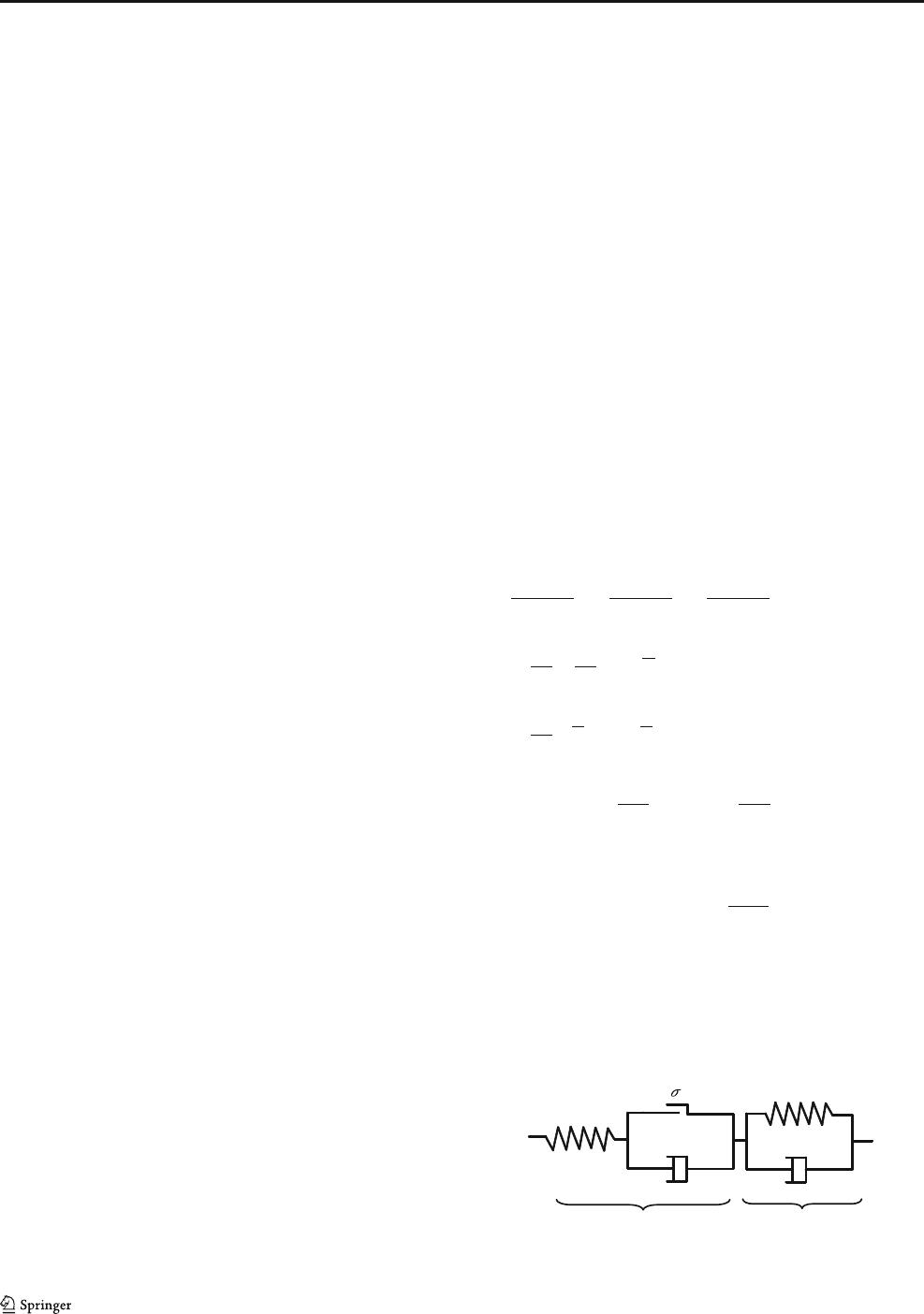
The Nishihara model composed of the Bingham and Kelvin
models in series is a rheological model with five elements as
showninFig.1.whereE
1
and η
1
respectively represent
Bingham model elastic coefficient and viscosity coefficient,
also E
2
and η
2
respectively represent the Kelvin model elastic
coefficient and viscosity coefficient, and σ
s
represent plastic
strength.
The plastic element in the Nishihara model is represented
by a switch. Plastic deformation in the model is determined by
stress; nevertheless, it is greater than the plastic strength σ
s
.
(1) Nishihara model rheological properties when σ < σ
s
The strain on the plastic element is zero, thus the stress is
restricted on the Bingham model’s viscous element. The mod-
el becomes the general Kelvin model with three elements. The
constitutive creep unloading and relaxation equations of the
model based on continuum theory are as follows:
σ þ
η
2
E
2
þ E
1
σ
˙
¼
E
2
E
1
E
2
þ E
1
ε þ
E
1
η
2
E
2
þ E
1
ε
˙
ð1Þ
ε tðÞ¼
σ
0
E
1
þ
σ
0
E
2
1−e
−
E
2
η
2
t
ð2Þ
ε tðÞ¼
σ
0
E
2
e
E
2
η
2
t
0
−1
e
−
E
2
η
2
t
ð3Þ
σ tðÞ¼E
∞
ε
0
1−e
−
E
2
þE
1
η
2
t
þ E
1
ε
0
e
−
E
2
þE
1
η
2
t
ð4Þ
where σ implies stress, ε implies strain, t implies rheology
time, t′ implies unloading time, σ
0
implies constant stress, ε
0
implies constant strain, and E
∞
¼
E
1
E
2
E
2
þE
1
.
(2) Nishihara model rheological properties when σ ≥ σ
s
Plastic deformation occurs in the plastic element subjected
to infinite strain and a constant strain rate, and the stress on
viscous element of the Bingham model becomes σ–σ
s
.The
1
E
1
E
2
2
s
Kelvin
Bin
g
ham
ηη
Fig. 1 Nishihara rheological model
559 Page 2 of 8 Arab J Geosci (2019) 12:559
constitutive creep unloading and relaxation equations of the
model based on continuum theory are as follows:
σ−σ
s
þ
η
1
E
1
þ
η
2
þ η
1
E
2
σ
˙
þ
η
1
η
2
E
1
E
2
σ
::
¼ η
1
ε
˙
þ
η
1
η
2
E
2
ε
::
ð5Þ
ε tðÞ¼
σ
0
E
1
þ
σ
0
−σ
s
η
1
t þ
σ
0
E
2
1−e
−
E
2
η
2
t
ð6Þ
ε tðÞ¼
σ
0
−σ
s
η
1
t
0
þ
σ
0
E
2
e
E
2
η
2
t
0
−1
e
−
E
2
η
2
t
ð7Þ
σ tðÞ¼
E
1
α−β
−
E
2
η
1
þ α
e
−αt
þ
E
2
η
1
−β
e
−βt
ε
0
þ
σ
s
M
e
−αt
α
−
e
−βt
β
þ σ
s
ð8Þ
where α ¼
p
1
þM
2p
2
; β ¼
p
1
−M
2p
2
; p
1
¼
η
1
E
1
þ
η
2
E
2
þ
η
1
E
2
; p
2
¼
η
1
η
2
E
1
E
2
;
M ¼
ffiffiffiffiffiffiffiffiffiffiffiffiffiffi
p
2
1
−4p
2
p
.
Nishihara model in the discrete element method
Due to the presence of a plastic element, the iterative calcula-
tion must be performed depending on the condition of contact
force ( f ) between two entities, if and only if exceeds the
plastic threshold f
s
(Yang et al. 2015).
(1) Numerical integration methods when f < f
s
The contact force f
t +1
between particles is
f
tþ1
¼
1
C
1
u
tþ1
−u
t
þ 1−
B
A
u
t
2
∓D
1
f
t
ð9Þ
where A ¼ 1 þ
E
2
Δt
2η
2
; B ¼ 1−
E
2
Δt
2η
2
; C
1
¼
Δt
2η
2
A
þ
1
E
1
;
D
1
¼
Δt
2η
2
A
−
1
E
1
; u
2
is the relative displacement of the Kelvin
model; u is the relative displacement of the Nishihara model;
Δt is the time step.
(2) Numerical integration methods when f ≥ f
s
The contact force f
t +1
between particles is
f
tþ1
¼
1
C
2
u
tþ1
−u
t
þ 1−
B
A
u
t
2
∓D
2
f
t
Δt f
s
η
1
ð10Þ
where A ¼ 1 þ
E
2
Δt
2η
2
; B ¼ 1−
E
2
Δt
2η
2
; C
2
¼
Δt
2η
2
A
þ
1
E
1
þ
Δt
2η
1
;
D
2
¼
Δt
2η
2
A
−
1
E
1
þ
Δt
2η
1
; u
2
is the relative displacement of the
Kelvin model; u is the relative displacement of the Nishihara
model; Δt is the time step.
Development of the user-defined model
Unique serial numbers of the model must be set up to avoid
conflict with the standard model before developing a user-
defined model in PFC. In the C++ language, the member
functions CM_vep::CM_vep(), CM_vep::Name(),
CM_vep::PropNames(), CM_vep::ReturnProp(),
CM_vep::AcceptProp(), CM_vep::FDlaw(), and
CM_vep::SaveRestore() of the source file need to be modi-
fied. Finally, source files are compiled into a dynamic link
library file (DLL file) and can be called by PFC.
Establishment of jointed rock mass model
In the PFC
3D
program, rock materials are represented by
bonded particles using bonded particle model. Particles are
characterized by sphere of rigid materials, which have friction
coefficient, normal stiffness, and tangential stiffness, while
bonding parts are elastic-brittle bodies.
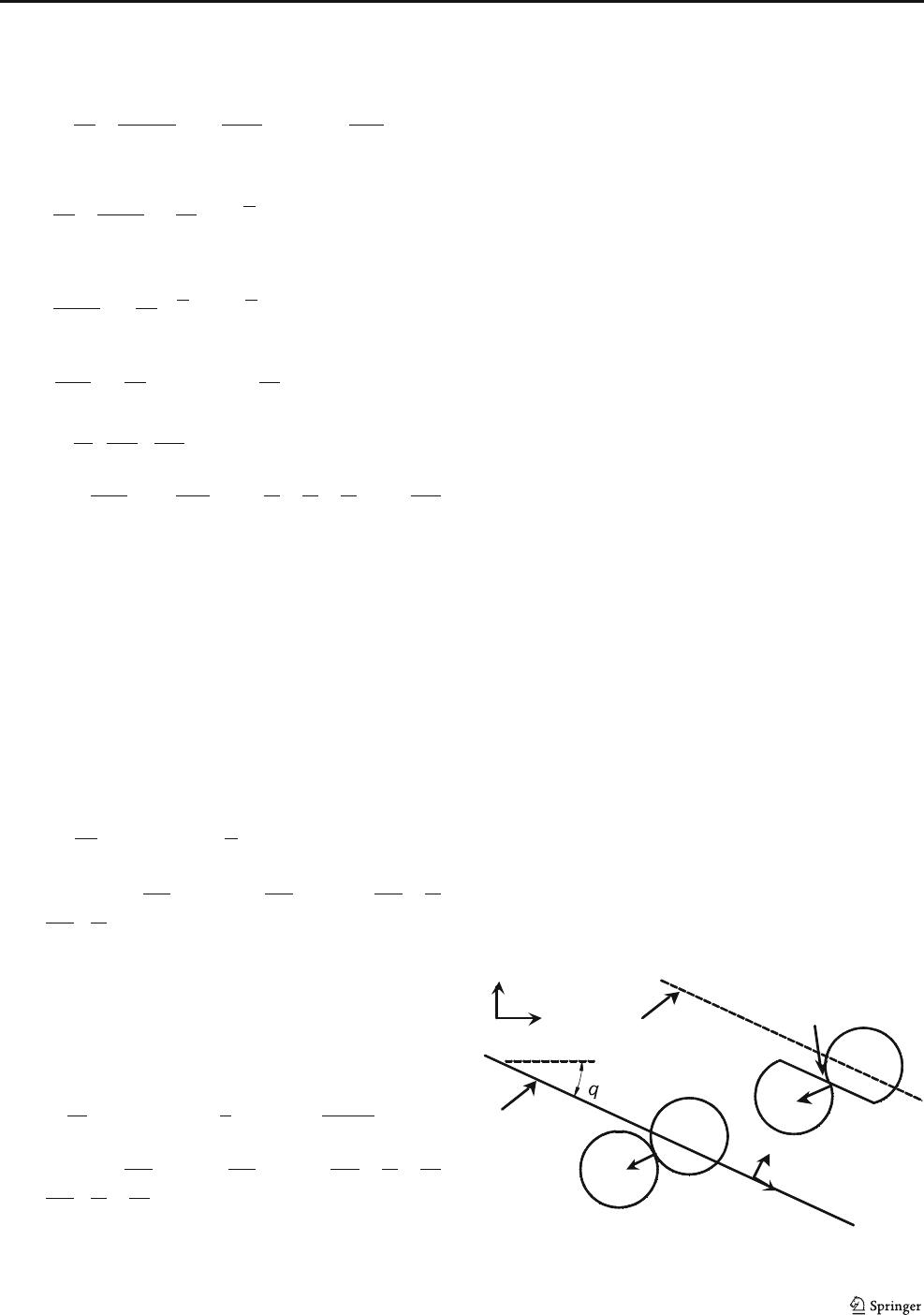
In Particle Flow Code, real joints are generally repre-
sented by a smooth joint model. Smooth joint model is
disc-shaped, which can generate arbitrary structural planes
in particles without considering the contact direction be-
tween particles. Smooth joint model allows two contact
particles to slide parallel along the structural plane, thus
eliminate the “bump” effect of particle sliding. This model
comprisesfaces1and2anddipangleθ, with directions
being defined by a unit normal vector n
j
and a shear vector
τ
j
,asshowninFig.2.
The smooth joint model is a disk in PFC
3D
,andthecontact
force F and displacement U between two particles are calcu-
lated as
U ¼ U
n
n
j
þ U
s
F ¼ F
n
n
j
þ F
s
ð11Þ
where U
n
and U
s
are the normal and shear displacement and
F
n
and F
s
are the normal and shear contact force. In an
J
oint plane
Surface 1
Joint plane
Surface 2
Ball 2
Smooth-joint mode
l
y
x
Ball 1
n
j
n
c
t
j
n
c
Fig. 2 Smooth joint model
Arab J Geosci (2019) 12:559 Page 3 of 8 559

iterative computation, the new contact force can be obtained in
terms of the elastic displacement increments ΔU
e
n
and ΔU
e
s
:
F
0
n
¼ F
n
−k
n
AΔU
e
n
F
0
s
¼ F
s
−k
s
AΔU
e
s
)
ð12Þ
where
k
n
and k
s
are the smooth normal and shear stiffness.
Principally, the establishment of the jointed rock mass
model in this paper consists of the following steps:
(1) Acquisition of joint orientation information. According
to survey lines arranged in the tunnel, joints exposed on
the hole walls were counted statistically, acquiring infor-
mation on number, dip angle, dip direction, and the trace
length of joints.
(2) Statistical analysis. This was carried out with the
orientation and position information of obtained
joints to confirm the distribution law for each ori-
entation element.
(3) Generation of random numbers. A random number
matrix with a special distribution law was generat-
ed using the random number generation functions
of Matlab.
(4) Reestablishment of joint network. Information of posi-
tion and orientation on fractures were combined with the
random numbers. A joint network was established in the
rock sample using the Monte Carlo method applied to the
smooth joint model in PFC
3D
.
(5) Synthesis of jointed rock mass model. The joint network
was inserted into an intact rock model established using
particles bonded by parallel bond model in order to syn-
thesize the jointed rock mass model.
Engineering application
Zhangjiawa iron mine is 3 km to the north of Laiwu
City, Shangdong Province of China. The rock mass in
the mining area is Yanshani an diorite and diorite. The
rock of the roof and floor in t h e ore body is relativ el y
hard, and the individual rock fissures are relatively de-
veloped; the stone in fissures is soft. The mine has a
deep aquifer, weak permeability, and poor hydraulic con-
nection with the surrounding, high hydrostatic pressure,
mainly static reserves, and simple hydrogeological con-
dition. The fault structure of the mining area is relatively
developed with the north-east direction being the main
and followed by the northwest direction. The surround-
ing rock is covered with lots of joints and fractures, and
the tunnels show a very large amount of deformation.
The tunnel deformation shows obvious creep character-
istic and high repair rate, with the result that it is diffi-
cult to support the roadways. Therefore, mining becomes
more and m ore difficult with increasing depth.
The uniaxial, triaxial, and uniaxial creep laboratory com-
pressive tests were carried out on the dry intact cylindrical
specimens with a size of φ50mm × 100 mm taken from
Zone One, Level–196 of the mine. The basic mechanical pa-
rameters of the rock were obtained to use in engineering cal-
culation and stability prediction as shown in Table 1.
Selection of calculation parameters
Rock strength parameters were obtained from laboratory tests
on samples collected in the field. As shown in Fig. 3, a particle
flow model with a radius of 50 mm and a height of 100 mm
Table 1 Mechanical properties
from laboratory tests and the
simulation
Compressive
strength σ
c
/MPa
Modulus of
elasticity E/GPa
Poisson’sratioμ Cohesion C/MPa Friction angle
φ/°
Experiment 23.76 9.37 0.27 3.29 28.4
Simulation 23.9 9.12 0.28 3.67 29.5
0.5
1.0
1.5
15
Strain (
μ
m·mm
-1
)
0
5
20
30
0.0
s
s
e
rtS(
aPM
)
2.52.0
10
25
Numercial simulation
Laboratory experiment
3.0
50 mm
100
mm
Fig. 3 Particle flow model and stress–strain curves
15
1.0
Time (h)
0.5
1.5
2.0
0
Aniarts
l
ai
x
(
μ
m·mm
-1
)
30
0.0
5
20
Experiment result
Simulation result
5 MPa
10 MPa
15 MPa
10
25
Fig. 4 Simulation of uniaxial compression creep experiment
559 Page 4 of 8 Arab J Geosci (2019) 12:559
was generated by Fishtank and given parallel bonds between
particles. After repeated debugging, the numerical sample was
in accord with the mechanical parameters of real rock sam-
ples, as shown in Table 1. Stress–strain curves from the labo-
ratory tests and the simulation are shown in Fig. 3.
A creep test was carried out with the user-defined Nishihara
constitutive model. Uniaxial compressive creep experiments
were carried out with the servo mechanism program; and 5,
10, and 15 MPa, the three step-by-step increasing stress level
was set to the axial compression. The axial strain of the sample
was recorded and is compared with the result of a laboratory
uniaxial compressive creep experiment in Fig. 4.
Based on transient tests and rheological tests, the rheolog-
ical meso-mechanical parameters shown in Table 2 were ob-
tained, and applied to deformation and stability calculations
for tunnels.
The minimum particle radius R
min
is 0.4 mm. The ratio
between the maximum and minimum particles radii is 1.66.
The particle density is 2250 kg/m
3
. μ is the particle friction
coefficient. E
c
is the particle elastic modulus. k
n1
/k
s1
is the
ratio of normal to shear stiffness. λ is the parallel bond radius
coefficient.
E
c
is the parallel bond elastic modulus. k
n2
/k
s2
is
the ratio of normal to shear parallel bond stiffness. σ
n,mean
and
σ
n,dev
are the mean and standard deviation of the parallel bond
normal strength. And τ
s,mean
and τ
s,dev
are the mean and stan-
dard deviation of the parallel bond shear strength.
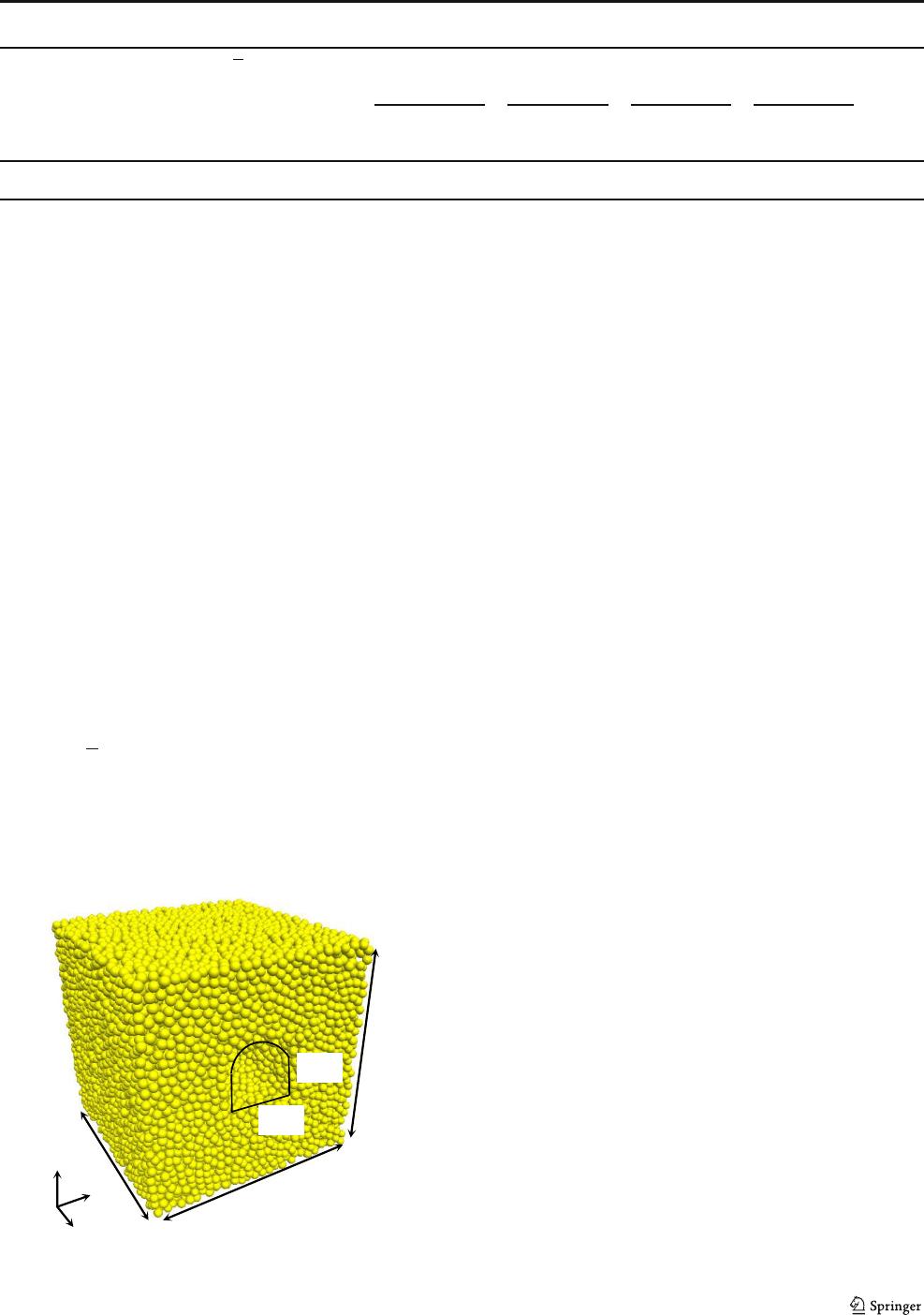
Establishment of tunnel model
Using the parameters in Table 2, a geological model was
established with a size of 10 m × 10 m × 10 m, and the width
and height of tunnel were both taken as 3.2 m, as shown in
Fig. 5.
Generation of joint network
Field statistics and distribution characteristics were ob-
tained on exposed joints in the tunnel. The results
showed that the dip angle and dip direction of joints in
the tunnel were normally distributed, wit h the orientation
parameters shown in Table 3.
The results of some studies have shown that it is rea-
sonable to regard the joint as a disk and a ssume that the
joint radius obeys a negative exponential distribution (Wu
et al. 2012). Using the random numbers obeying such a
distribution from Matlab, a jointed rock mass model in-
cluding the Nishihara rheological constitutive model and
the embedded smooth joint model was generated using
network reestablishment by the Monte Carlo method, as
shown in Fig. 6.
The mechanical parameters of the smooth joint model were
obtained using joint roughness and hardness values obtained
from engineering geological exploration and rock joint me-
chanical tests, as shown in Table 4.
Rheological properties of a jointed rock mass
Tunnel damage was modeled using the parameters obtained
above. Li et al. (2010) obtained the following relationship
between the maximum horizontal principal stress and vertical
principal stress in the Zhangjiawa mine:
σ
H
¼ 1:4∼1:3ðÞγH ð13Þ
where σ
H
is the maximum horizontal principal stress. γ is the
specific weight of the rock, and H is the depth. The depth was
400 m with a vertical stress of 9 MPa and a horizontal stress of
12 MPa.
Table 2 Meso-mechanical parameters of numerical specimen
μ E
c
/GPa k
n1
/k
s1
λ E
c
/GPa k
n2
/k
s2
Parallel bond
normal strength
Parallel bond
shear strength
Bingham
model
Kelvin
model
σ
s
/MPa
σ
n,mean
/
MPa
σ
n,dev
/
MPa
τ
s,mean
/
MPa
τ
s,dev
/
MPa
E
1
/
MPa
η
1
/
MPa s
E
2
/
MPa
η
2
/
MPa s
0.52 8 3.1 1.0 8.25 3.1 25 ± 5.0 30 ± 5.0 45 3 × 10
6
45 4 × 10
4
15
10 m
10
m
3.2 m
3.2 m
z
y
10 m
x
Fig. 5 PFC calculation model
Arab J Geosci (2019) 12:559 Page 5 of 8 559
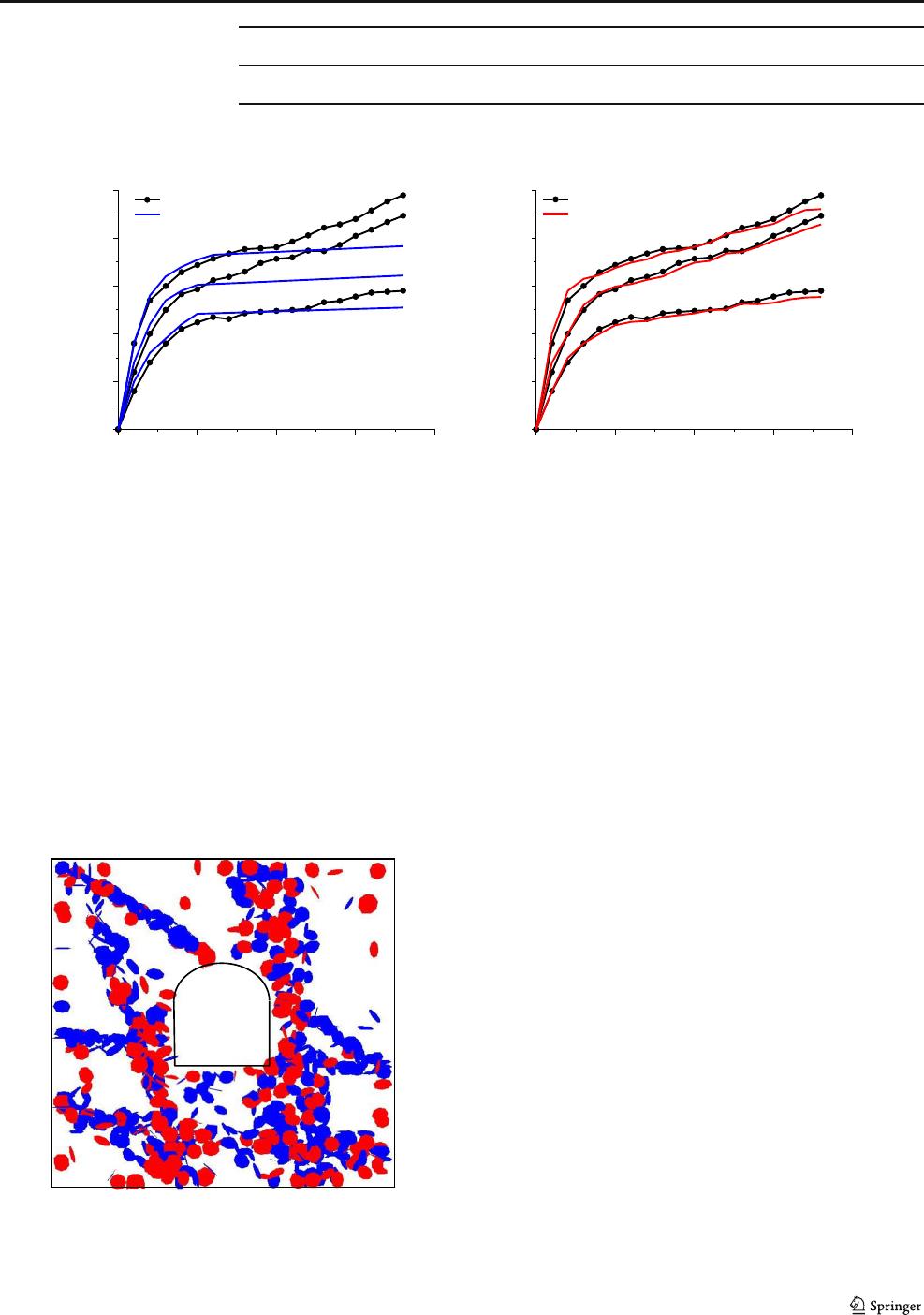
Analysis of tunnel deformation characteristics
To ensure productive safety, displacement monitoring was
carried out at Level–196 of the No. 11 branch tunnel of the
Zhangjiawa iron mine to monitor the displacements of the roof
and left and right sides. According to the analysis of the mon-
itoring data, the roadway exhibited creep property with a dis-
placement of 0.5 mm per day in the roof, 1 mm per day in the
right side, and 0.8 mm per day in the left side.
Tunnel deformation of a jointed rock mass was calculated
with the linear elastic mode l and Nishihara model using
PFC
3D
. The correlation curves between simulation and mon-
itoring results are shown in Fig. 7a, b for the respective
models. As can be seen, with the linear elastic model, both
sides and the roof were stable and did not change with time,
showing no creep property. In contrast, with the Nishihara
model, creep property was obvious, and the trend of variation
was in accord with the monitoring results.
Tunnel deformation can be divided into the following main
stages:
(1) Instant elastic and plastic deformation: owing to the re-
lease of the original rock stress and the extrusion of the
surrounding rock as the tunnel is excavated, the tunnel
shrinks instantaneously and a secondary stress field is
formed with stress redistribution.
(2) Slow deformation: instantaneous elastic–plastic defor-
mation has more or less finished about 2–3daysafter
formation of the tunnel. Because partial stress has not
been completely released , contractive deformation of
the tunnel continues.
(3) Initial creep stage: the stress has now been released about
4–5 days after formation of the tunnel. Owing to the
creep effect, deformation continues and enters the initial
stage of creep.
(4) Stable creep stage: deformation is the same every day
about 6 days after formation of the tunnel, and the
cross-sectional area of the tunnel slowly contracts at a
certain rate.
Analysis of tunnel failure mode
According to the field survey, tunnel damage is related closely
to the joint surface. Tunnels with developed joint surfaces are
damaged most severely with several numerous supports des-
quamating, as are their surroundings.
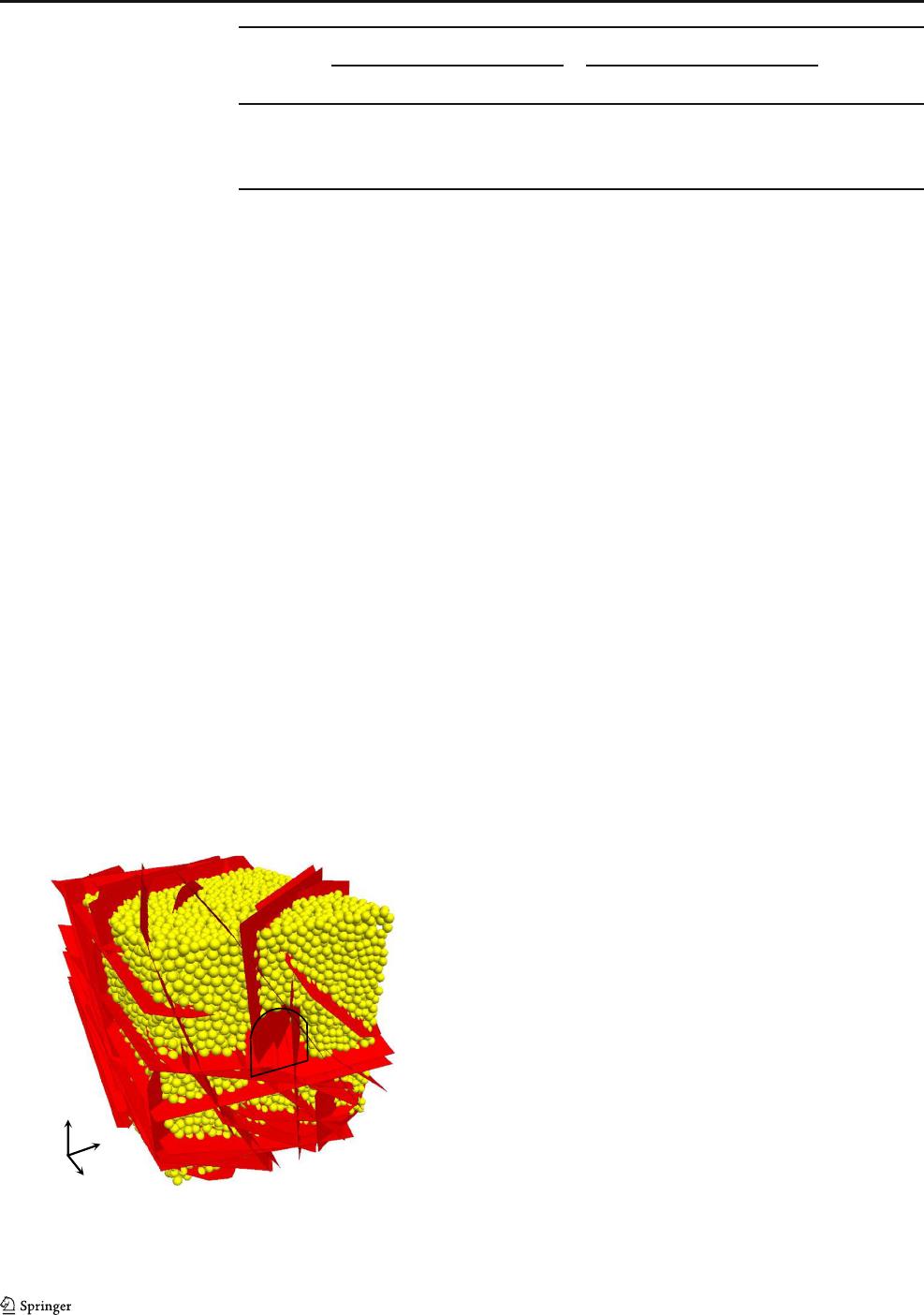
To analyze tunnel failure, the jointed rock mass model was
adopted in PFC with the result shown in Fig. 8, where blue
color represents shear failure and red color represents tension
failure. The bonds of the joint faces were damaged primarily
by shear failure. The damaged areas without joints were main-
ly subject to tension failure. The tunnel walls were damaged
severely as a result of stress concentration. The damage to the
tunnel surroundings predicted by the model that was in close
accord with the result of the field survey.
Suggestion for treatment
The tunnel deformation analysis using the rheological proper-
ties of a jointed rock mass indicates that there is a large hori-
zontal stress with a creep effect, causing more severe damage
on the two sides of the tunnel. Therefore, with regard to long-
term stability, it is necessary to strengthen the supports on both
sides using bolts and cables.
Table 3 Orientation parameters
of joints
Orientation Dip angle Dip direction Bulk density/
strip m
–3
Mean value/° Standard deviation/° Mean value/° Standard deviation/°
Group A 73 5 57 3 0.023
Group B 21 5 10 3 0.012
Group C 58 5 69 3 0.025
z
y
x
Fig. 6 Jointedrockmassmodel
559 Page 6 of 8 Arab J Geosci (2019) 12:559
Conclusions
Based on PFC
3D
, a Nishihara rheological constitutive model
with visco-elastoplastic properties was constructed to investi-
gate the rheological properties of a jointed rock mass. The
main conclusions of this study are as follows:
(1) The constitutive creep unloading and relaxation equa-
tions of the Nishihara model were studied based on the
continuum theory, and the Nishiha ra model was
extended to the discrete element method. Deduced was
the iterative relationship between the force and displace-
ment and the numerical integration method of the model.
(2) The Nishihara rheological constitutive model suitable for
the PFC program was developed. The particle flow block
model was combined with the joint network model to
establish a numerical model of jointed rock mass based
on the Nishihara constitutive model.
(3) Tunnel deformation was calculated with the linear elastic
model and the Nishihara model. According to the linear
elastic model, the roof and both sides of the tunnel be-
came stable and did not change with time showing any
creep property, but the result of the Nishihara model
showed obvious creep property and was in accord with
monitoring result from the field.
(4) Analysis of tunnel damage behavior showed that the
bonds of the joint faces were damaged primarily due to
shear failure in the jointed rock mass model. As a result
of stress concentration near the tunnel walls, damage
extended to the surroundings in close accord with the
field survey result.
(5) This user-defined constitutive model developed based on
PFC is a reliable tool for describing the rheological prop-
erty of samples especially combined with laboratory ex-
periments, thereby providing a basis for guidance on
tunnel supports.
10
30
Time (day)
15
45
60
0
Dnoitamrofe(mm)
20
0
515
Monitoring result
Linear Elastic Model
roof
Left side
Right side
75
10
30
Time (day)
15
45
60
0
Dnoitamrofe(
mm
)
20
0
515
Monitoring result
Nishihara model
roof
Left side
Right side
75
(a) Calculation with the linear elastic model (b) Calculation with the Nishihara model
Fig. 7 Deformation monitoring of tunnel
Table 4 Mechanical properties of
smooth joint model
Normal stiffness/GPa Shear stiffness/GPa Friction angle/° Expansion angle/° Cohesion/MPa
100 20 30 0 12.5
Fig. 8 Failure mode of tunnel
Arab J Geosci (2019) 12:559 Page 7 of 8 559

Acknowledgments The authors would like to acknowledge Mr. Han
Ying and Mr. Kong Zheng of Zhangjiawa Iron Mine for their help in field
investigations. The authors would l ike to acknowledge Mr. Mataita
Charles for his help in polishing the English. The authors would also like
to acknowledge all the reviewers and editors for their great contribution
towards improvements of the manuscript.
Funding information The research presented in this paper was supported
by the Natural Science Foundation of China (Grant No. 51674015) and
Beijing Training Project for the Leading Talents in S & T (Grant No.
Z151100000315014).
References
Cundall PA, Strack ODL (1979) A discrete numerical model for granular
assemblies. Geotechnique 29(1):47–65
Di SJ, Xu WY, Ning Y, Wang W, Wu GY (2011) Macro-mechanical
properties of columnar jointed basaltic rock masses. J Cent S Univ
Techno l 1 8(6):2143–2149. https://doi.org/10.1007/s11771-011-
0955-4
Dowd PA, Martin JA, Xu C, Fowell RJ, Mardia KV (2009) A three-
dimensional fracture network data set for a block of granite. Int J
Rock Mech Min Sci 46(5):811–818. https://doi.org/10.1016/j.
ijrmms.2009.02.001
Huang TH, Chang CS, Yang ZY (1995) Elastic moduli for fractured rock
mass. Rock Mech Rock Eng 28(3):135–144
Ivars DM, Pierce ME, Darcel C, Montes JR, Potyondy DO, Young RP,
Cundall PA (2011) The synthetic rock mass approach for jointed
rock mass modelling. Int J Rock Mech Min Sci 48(2):219–244.
https://doi.org/10.1016/j.ijrmms.2010.11.014
Kang DH, Yun TS, Lau YM, Wang YH (2012) DEM simulation on soil
creep and associated evolution of pore characteristics. Comput
Geotech 39(1):98–106. https://doi.org/10.1016/j.compgeo.2011.09.
003
Kulatilake PHSW, Malama B, Wang J (2001) Physical and particle flow
modeling of jointed rock block behavior under uniaxial loading. Int
J Rock Mech Min Sci 38(5):641–657. http s://doi.org/10.1016/
S1365-1609(01)00025-9
Li YS, Xia CC (2000) Time-dependent tests on intact rocks in uniaxial
compression. Int J Rock Mech Min Sci 37(3):467–475
Li WX, Wang SS, Liu L, Meng QL, Liu XM, Mei SH (2010)
Measurement analyses of rock mass movement and deformation
due to underground mining of deep fractured ore body in
Guanzhuang iron mine. Chin J Rock Mech Eng 29(4):681–688
Li N, Cao P, Yi YL, Zhang XY (2011) Creep properties experiment and
model of deep rock with step loading and unloading. J Cent South
Univ Sci Technol 42(11):3465–3471
Liu L, Wang GM, Chen JH, Yang S (2013) Creep experiment and rheo-
logical model of deep saturated rock. Trans Nonferrous Metals Soc
China 23(2):478–48 3. http s://doi.org/10.1016/S1003-6326(13)
62488-7
Pedersen RR, Simone A, Sluys LJ (2008) An analysis of dynamic fracture
in concrete with a continuum visco-elastic visco-plastic damage
model. Eng Fract Mech 75(13):3782–3805. https://doi.org/10.
1016/j.engfracmech.2008.02.004
Qi YJ, Jiang QH, Wang ZJ, Zhou CB (2012) 3D creep constitutive equa-
tion of modified Nishihara model and its parameters identification.
Chin J Rock Mech Eng 31(2):347–355
She CX (2009) Research on nonlinear viscoelasto-plastic creep model of
rock. Chin J Rock Mech Eng 28(10):2006–2011. https://doi.org/10.
3969/j.issn.1673-9469.2017.04.006
Tao B, Wu FQ, Guo GM, Zhou RG (2005) Flexibility of visco-
elastoplastic model to rheological characteristics of rock and solu-
tion of rheological parameter. Chin J Rock Mech Eng 24(17):3165–
3171
Wang YY, Wang YC (2012) Numerical simulation of creep law in deep
soft rock tunnel under thermal-mechanical-chemical coupling effect.
J China Coal Soc 37(a02):275–279
Wang JC, Chang LS, Chen YJ, Xiao H (2005) 3-D network simulation
and probability damage tensor analysis of joint rock mass in open
iron mines. J Univ Sci Technol Beijing 27:1):1–1):4
Wang T, Lu Q, Li Y, Li HM (2009) Development of contact model in
particle discrete element method. Chin J Rock Mech Eng 28(a02):
4040–4045
Wu SC, Zhou Y, Gao LL, Zhang XP (2010) Application of equivalent
rock mass technique to rock Mass engineering. Chin J Rock Mech
Eng 29(7):1435–
1441
Wu SC, Zhou Y, Gao YT, Misra A (2012) Research on construction
method of stochastic joints 3D-network model of equivalent rock
mass. Chin J Rock Mech Eng 31(a01):3082–3090
Xu C, Dowd P (2010) A new computer code for discrete fracture network
modeling. Comput Geosci 36(3):292–301. https://doi.org/10.1016/j.
cageo.2009.05.012
Xu WY, Wang RB, Wang W, Zhang ZL, Zhang JC, Wang WY (2012)
Creep properties and permeability evolution in triaxial rheological
tests of hard rock in dam foundation. J Cent South Univ 19(1):252–
261. https://doi.org/10.1007/s11771-012-0999-0
Yang SQ, Jiang YZ (2010) Triaxial mechanical creep behavior of sand-
stone. Min Sci Technol 20(3):339–349. https://doi.org/10.1016/
S1674-5264(09)60206-4
Yang SL, Zhang JM, Huang QP (2004) Analysis of creep model of
jointed rock. Rock Soil Mech 25(8):1225–1228
Yang ZW, Jin AB, Wang K, Meng XQ, Gao YJ (2015) Development and
application of a visco-elastoplastic constitutive model in particle
flow code. Rock Soil Mech 36(9):2708–2715. https://doi.org/10.
16285/j.rsm.2015.09.035
Zhang CH, Yu YJ, Yue HL, Zhao QS (2010) Model with random cleats
distribution for coal seams and its application. Rock Soil Mech
31(1):265–270
Zhang HB, Wang ZY, Zheng YL, Duan PJ, Ding SL (2012a) Study on tri-
axial creep experiment and constitutive relation of different rock salt.
Saf Sci 50(4):801–805. https://doi.org/10.1016/j.ssci.2011.08.030
Zhang ZL, Xu WY, Wang W, Wang RB (2012b) Triaxial creep tests of
rock from the compressive zone of dam foundation in Xiangjiaba
Hydropower Station. Int J Rock Mech Min Sci 50(1):133–139.
https://doi.org/10.1016/j.ijrmms.2012.01.003
Zhang Y, Xu WY, Gu JJ, Wang W (2013) Triaxial creep tests of weak
sandstone from fracture zone of high dam foundation. J Cent South
Univ 20(9):2528–2536. https://doi.org/10.1007/s11771-013-1765-7
Zhao YL, Cao P, Wang WJ, Wan W, Liu YK (2009) Viscoelasto-plastic
rheological experiment under circular increment step load and un-
load and nonlinear creep model of soft rocks. J Cent S Univ Technol
16(3):484–491. https://doi.org/10.1007/s11771-009-0082-7
Zhou Y, Wang L, Ding JF, Wu HY (2016) Particle flow code analysis of
multi-scale jointed rock mass based upon equivalent rock mass tech-
nique. Rock Soil Mech 37(7):2085–2095. https://doi.org/10.16285/
j.rsm.2016.07.033
559 Page 8 of 8 Arab J Geosci (2019) 12:559
