169
Mater. Res. Soc. Symp. Proc. Vol. 1492 © 2013 Materials Research Society
DOI: 1 557/op 0130.1 l.2 .
Mullite Formation in Al
2
O
3
/SiO
2
/SiC Composites for Processing Porous Radiant Burners
Daphiny Pottmaier, Jefferson J. Rosario, Marcio C. Fredel, Amir A.M. Oliveira,
Orestes E. Alarcon
Mechanical Engineering Department, Federal University of Santa Catarina,
Caixa Postal 476 Campus Trindade, 88040-900 Florianopolis, Brazil.
ABSTRACT
Use of porous ceramic burners for natural gas combustion is an optimum alternative to
enhance energy efficiency and decrease emission of pollutant gases per generated power.
Materials requirements for the operation of such porous burners are mainly thermal shock and
chemical resistance and those can be reached with cellular ceramics. Mullite was theoretically
identified among the best materials for this application; however, its potential was not properly
explored yet. Even though mullite can be synthesized from different compounds and processing
routes, control of final material characteristics is complicated mainly due to the formation of
amorphous phase. In this work, using a technological approach mullite burners were processed
by the replication method starting from different mixtures of Al
2
O
3
/SiO
2
/SiC. Rheological study
of the slurries has given additives content for the coating of the polyurethane sponges. After
varying sintering temperatures up to 1600 °C and isotherm times for 12 h, microstructural
aspects and product phases of the final composites were characterized in order to understand the
influence of Al
2
O
3
/SiO
2
/SiC ratios in the formation of mullite phase and amorphous content.
INTRODUCTION
Porous medium combustion using radiant ceramic burners combined with natural gas is
and optimum alternative to enhance energy efficiency of the combustion processes as it results in
uniform and infrared heating with extension of lean flammability and higher burning rates with
lower emission of pollutant gases [1]. That also means economic advantage as it lowers gas
consumption per generated power. Combustion inside a porous structure requires specific
properties from its constituent materials during operation. Materials for porous burners must
resist principally to thermo mechanical stress due to high temperature gradients and corrosion
effects depending on the fuel type, ratio and pressure. Additionally, low-priced raw materials are
necessary for the fabrication of simple components in many domestic and industrial applications.
Cellular ceramics suitably attend the required properties as a function of porosity percentage and
morphology, porous distribution and type. Such characteristics may vary depending on the
constituent materials (i.e. pure, mixture, composite) and their processing (e.g. replication,
foaming, gelation). The most used materials in porous burner systems are: silicon carbide (SiC)
due to good thermal transport up to 1350 ºC and other outstanding properties [2], aluminum
oxide (Al
2
O
3
) for temperatures up to 1900 ºC [3], zircon oxide (ZrO
2
) for temperatures up to
320

170
2300 ºC [4], Fe-Cr-Al alloys used for lower temperatures and high thermal shock resistances [5].
They can also be fabricated with other materials such as corderite [6-8] and other approaches
such as using aggregates or fibers [9].
Previous studies in our laboratory were performed using the replication method for
processing of Li
2
O-ZrO
2
-SiO
2
-Al
2
O
3
(LZSA) glasses [10-12], ZrO
2
[13], Al
2
O
3
[14], and
recently for SiC-based foams [15-17] similarly to Zhu et al. [18-20]. From these analyzed porous
systems, limitations assigned are thermal shock resistance of SiC and Al
2
O
3
, production costs of
ZrO
2
and operation temperatures of LZSA. Requirements such as higher operation temperatures
and lower pollutant emissions, for a more efficient application of the porous combustion
technology, moved our efforts to study other materials. Taking into account properties, process,
materials price and furnace set-up, mullite (3Al
2
O
3
.2SiO
2
to 2Al
2
O
3
.SiO
2
) burners can be
considered an optimal alternative and still underestimated for such application [21, 22]. A
detailed materials selection for the design of porous burners is given elsewhere [23]; considering
advanced modeling of fluid flow, heat generation from chemical reactions, and heat transfer
inside the burner structure. Formation of bulk mullite is a complex process that depends strongly
on the synthesis method and its precursors. Both solid (sinter-mullite) and liquid (fuse-mullite)
state reactions are influenced by powder characteristics, heat treatment, and Al
2
O
3
/SiO
2
ratio.
The crystal structure of mullite is orthorhombic, space group Pbam, with a large range of solid
solution, from 3Al
2
O
3
.2SiO
2
to 2Al
2
O
3
.SiO
2
is based on the substitution of 2Si
4+
+ O
2-
= 2Al
3+
on the tetrahedral sites [24]. Crystal morphology can be categorized in several types, such as
granular, cuboidal, acicular, or needlelike; with aspect ratio varying according to the viscosity of
the eutectic liquid and as a function of alkali content (Na
2
O, K
2
O) [25]. Addition of other
compounds might be not effective in growing specific morphologies but can significantly
increase its conversion rate. For example, only 20 % mullite was produced in the air heated
sample, but 96 % mullite was reached in the presence of SiF
4
[26]. Furthermore, mullite can be
formed by gaseous state processes such as chemical vapor deposition; for coating of SiC [27-29].
Finally, in this work , it was used an approach co-relating materials composition and
microstructure of mullite-based systems to fabricate porous burners in order to resist high
temperatures and harsh environments. Therefore, characterization results of the final composites
herein are concisely discussed on the light of its materials technological application.
MATERIALS AND METHODS
Starting materials suppliers are listed in Table 1 together with composition of the
Al
2
O
3
/SiO
2
/SiC suspensions. Commercial polyurethane (PU) sponges were impregnated with 7
ppi (Crest Foam Industries, United States of America). Particle size distribution of precursor
powders was obtained with a ZS Zetasizer (Malvern Instruments, United Kingdom).
Table 1. Starting materials suppliers and composition of Al
2
O
3
/SiO
2
/SiC suspensions.
Al
2
O
3
SiO
2
SiC colSil BTE’ CMC’’
Supplier
Sample Alcoa
Treibacher
Schleifmittel
Sigma
Aldrich
Schumacher
Insumos EMFAL
(1) Al
2
O
3
/ SiO
2
72.0 28.0 - 65.3 2.0 0.75
(2) Al
2
O
3
/ SiC 72.0 - 28.0 - 1.5 0.5
(3) Al
2
O
3
/ SiO
2
/ SiC 72.0 14.0 14.0 32.7 2.0 0.75
(4) SiC /Al
2
O
3
/ SiO
2
20.0 7.0 70.0 21.5 1.0 0.25
’ – Bentonite ’’– Carboxy Methyl Cellulose
171
Process flow of the replication method for the fabrication of the porous burners:
(1) water suspensions of the precursor materials were prepared by ball milling using 1/3 of
alumina balls, at 200 rpm for 24 hours; rheological studies of the suspensions performed with a
Haake VT 550 (Thermo Fisher, United States of America). (2) Slurry immersion and
impregnation was made using a home-made system. (3) Drying at ambient temperature for 24
hours. (4) Heating up to 850 ºC at 1 ºC/min for the extraction of the PU foam and organic
additives in a muffle with exhaustion system (Irmaos Sanchis & Cia Ltda, Brazil).(5) Sintering at
temperatures up to 1600 ºC at 5 ºC/min in a bottom loading furnace (Micropyretics Heaters
International Inc., United States of America).
Thermogravimetric data were acquired with a Q 500 (TA instruments, United States of
America) and dilatometry with a DIL 402C (Netzsch Group, Germany) in gas flow of 100
mL/min. Structural investigation was performed with XRD diffractometer X’Pert (Philips
PANalytical, Netherlands) and microstructural analysis in a SEM XL30 (Philips, Netherlands).
RESULTS AND DISCUSSIONS
Starting Materials
Information related to the physical characteristics of the commercial powders is given in
Table 2. High purity Al
2
O
3
and SiC powders, confirmed by XRD patterns (not shown), without
any additional treatment were used in the preparation of the composite materials. Particle size
was also verified using an optical granulometry technique (not shown) in which Al
2
O
3
presents a
broad trimodal particle size distribution and SiC a sharper unimodal profile.
Table 2. Physical characteristics of precursor powders.
Al
2
O
3
SiC SiO
2
Purity (wt.%) 99.6 98.5 -
Av. particle size (nm) 35 371 8
BET surface area (m
2
.g
-1
) 1.5 - 375.0
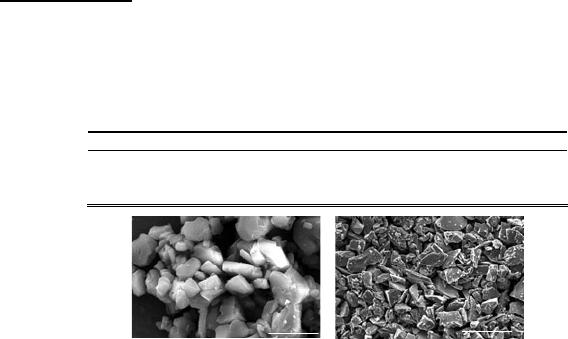
Figure 1. SEM micrographs of precursor Al
2
O
3
(left) and SiC (right) powders.
Figure 1 shows a uniform morphology of the starting powders as resulting from SEM
analysis. Al
2
O
3
particles presented a facetted-barrel shape typical of its hexagonal corundum
phase, while SiC particles are more angular with a plate-like shape and higher aspect ratio. Thus,
anisotropy of SiC particles might play a role during materials packing and sintering in order to
compensate its larger size and diffusion path compared to other precursors. In addition, thermal
analysis of the commercial PU sponge (not shown) was performed and it revealed a profile of
decomposition reactions with broad exothermic peaks between 250 ºC and 350 ºC and sharp
peak at 525 ºC; with gradual mass loss up to 900 ºC and final carbonaceous residues of about
3.5 wt.%.
100 μm
15 kV 250x5 μm15 kV 5000x
172
Slurries Behavior
Suitable rheological behavior of the Al
2
O
3
/SiO
2
/SiC suspensions (Table 1) for the
impregnation of PU foams were obtained using Bentonite (BTE) as thickening agent and
Carboxy Methyl Cellulose (CMC) as dispersant. The specification given by Studart et al. [30]
was used as guideline, where viscosity should be 10 to 30 Pa.s at 5 s
-1
shear rate and 1 to 6 Pa.s
at 100 s
-1
shear rate. Composition 4 was already studied using the same starting materials [15-
17], thus it was promptly used in this work. The same systematic approach was followed to
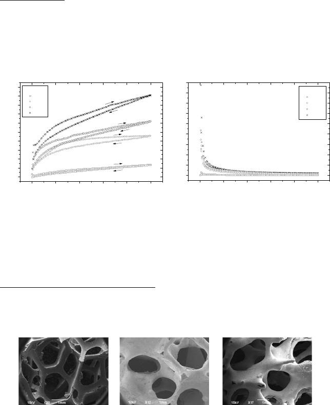
obtain the right additives proportion for the other compositions. As example, Figure 2 shows
rheological profiles of the suspensions as a function of additive content for composition 1.
CMC wt.%:
0.25
0.50
0.75
1.00
0 100 200 300 400 500
0
100
200
300
400
500
600
700
800
900
1000
Shear Stress / Pa
Shear Rate/ s
-1
0 100 200 300 400 500
0
10
20
30
40
50
60
70
80
90
CMC wt.%:
0.25
0.50
0.75
1.00
Viscosity / Pa.s
Shear Rate / s
-1
Figure 2. Al
2
O
3
-SiO
2
(1) slurry with BTE 2.0 wt.%: flow curves (a) and viscosity (b) per shear rate.
Figure 2a shows a pseudoplastic behavior of the slurry characterized by an increase in
shear stress along with increase of shear rate. A thixotropic behavior can be characterized by the
hysteresis on that curve. Figure 2b shows the behavior of viscosity with increasing shear rate,
pseudoplastic and thixotropic behavior can also be observed in these curves due to the decrease
of viscosity with increase of shear rate and the presence of hysteresis, as previously mentioned.
Sintering Profile and Structural Evolution
Figure 3 shows for comparison SEM micrographs of PU sponge as received, impregnated
after burning and after sintering. It is observed a sharp skeleton of initial PU sponge with angular
struts. After burning of the sacrificial template, the foam structure is formed by hollow struts
together within holes resulting from the polymer evaporation. A more interconnected body is
obtained for the sintered samples with rounded holes.
a b c
Figure 3. PU sponge as such (a), impregnated after burning (b) and after sintering (c).
Samples thermal behavior was studied coupling dimensional changes and weight changes
(not shown) together with phase evolution (Figure 4) of the sintering process. Sintering profiles
have shown a directly proportional relationship of colloidal silica content and both weight loss
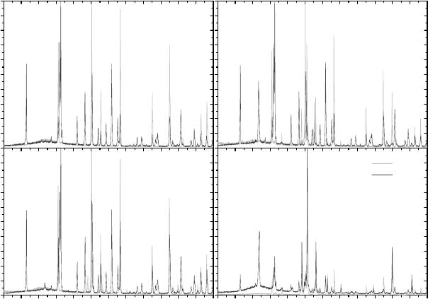
173
and dimensional contraction. Crystalline phases were identified together with amorphous content
from XRD patterns of samples sintered at 1150 ºC and 1600 ºC.
0.0
0.1
0.2
0.3
0.4
0.5
0.6
0.7
0.8
0.9
1.0
10 15 20 25 30 35 40 45 50 55 60 65 70
10 15 20 25 30 35 40 45 50 55 60 65 70
10 15 20 25 30 35 40 45 50 55 60 65 70
0.0
0.1
0.2
0.3
0.4
0.5
0.6
0.7
0.8
0.9
1.0
10 15 20 25 30 35 40 45 50 55 60 65 70
A
A
M,A
A
M
M
A
A
M
M
M
M
A
A
A
M,A
M,A
M,A
A
O
M
M
M
M
Relative Intensity / a.u.
M
(1)
(2)
M
M
A
A,S
M
M,A
M
M
A,S
A
S
A
M
M
A
S
A,S
S
M
A
M
O
M
S
M
(3)
A
A
M,A
A
M
M
A
A
M
M
M
M
A
A
A
M,A
M,A
M,A
A
O
M
M
M
M
2 theta / de
g
ree
M
(4)
1150 C
1600 C
A
A
M
M,A
M
M
M
A,S
A
S
A
M
M
A
S
A,S
S
M
S
A
M
O
M
S
M
Figure 4. XRD patterns of: (1)Al
2
O
3
-SiO
2
, (2) Al
2
O
3
-SiC, (3)Al
2
O
3
-SiO
2
-SiC, (4)SiC-Al
2
O
3
-SiO
2
. M=
mullite, A= alumina, S= silicon carbide, O= silica.
Crystalline phases were assigned by their general names as solid solution may occur [31,
32], and therefore, dislocation of peaks positions are regularly observed for alumina and mullite
phases. Alumina grains will disintegrate in the dissolution process due to Si
+4
diffusion into
Al
2
O
3
, starting in the glassy interface [33]. Thus, development of mullite and other
aluminosilicates with similar crystal structure is accompanied by saturation of alumina phase.
Such structural evolution is pronounced for samples 1, 2 and 3 with Al/Si ratio closer to mullite
stoichiometry (Figure 4b). Another phenomenon occurring in parallel is the insertion of Al with
both oxidation and amorphization of SiC [34]. This is suggested by the higher amorphous
content of SiC-based samples 2 (Al
2
O
3
-SiO
2
-SiC) and 4 (SiC-Al
2
O
3
-SiO
2
). Additionally, the
presence of small peaks suggests formation of other minor crystalline phases from the tripe
junctions of Al
2
O
3
-SiO
2
-SiC grains as recently reported in the literature [35].
174
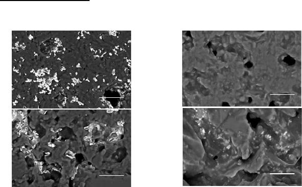
Microstructural Aspects
Figure 5 shows SEM micrographs, in back-scattered electrons mode, of the polished
surface for samples sintered at 1600 ºC under air atmosphere.
(a)
(b)
(c)
(d)
Figure 5. SEM of: (a) 1.Al
2
O
3
-SiO
2
, (b) 2.Al
2
O
3
-SiC, (c) 3.Al
2
O
3
- SiO
2
-SiC, (d) 4.SiC-Al
2
O
3
-SiO
2
.
A more uniform microstructure consisting of homogeneously distributed phases is
observed for composites 1 and 4. On the other hand, samples 2 and 3 presents an eye-visible
gradient of phase from the surface to the center. Sharp facets of SiC particles are noticeably in
samples 2 and 4, those with higher content of initial SiC (sample 4 > 2 > 3 > 1). Other feature
observed by the SEM analysis is lower porosity and presence of intrinsic cracks for the
composites with higher content of colloidal SiO
2
(sample 1 > 3 > 4 > 2).
CONCLUSIONS
Emphasis was given to find a simple and economical approach for processing mullite
porous burners of high performances. Thus, formation of mullite and control of microstructural
features were accompanied in order to obtain composites with the required properties.
Optimum rheology of the slurries for sponges impregnation was reached with additives
content between 2.75 to 1.25 wt.% in a fixed 80/20 ratio of water to solid. Sintering profiles by
dilatometry showed a contraction of 2.3 (sample 4) to 20.9 % (sample 1) and thermogravimetry a
change in weight of + 2.0 (sample 4) to -18.0 wt.% (sample 1). Composite samples sintered at
1600 °C presented 26 (sample 4) to 82 (sample 2) wt.% of mullite phase and 35 (sample 2) to 54
(sample 1) wt.% of amorphous content. Accordingly, scanning electron micrographs of
composites sintered at 1600°C have shown a phase gradient from shell to core as a function of
colloidal silica (sample 1 > 3 > 4 > 2).
In addition, porous burners based in the Al
2
O
3
- SiO
2
-SiC system are also being processed
and characterized with the incorporation of residual ashes from coal combustion.
10 μm
2000x 15kV
10 μm
2000x 15kV
10 μm
2000x 15kV
10 μm
2000x 15kV

175
ACKNOWLEDGMENTS
Authors thank CAPES, CNPq, Petrobras for financial support; M. Petry, G. Senem, M. Leite, C. da Silva,
R. Guimarares of CERMAT; J. F. Martins and M. Amorin of MAGMA; I. Mocellin and G. Hammes of
LABMAT for technical assistance; and P. B. Prates of LCM for fruitful discussions.
REFERENCES
1. R. Viskanta, in Handbook of Porous Media, edited by K. Vafai (Taylor & Francis, New York, 2005).
2. A. Fuessel, H. Klemm, D. Boettge, F. Marschallek, J. Adler, A. Michaelis, IOP conf series in Ceram.,
Osaka (2011).
3. C. Tierney and A.T. Harris, Journal of the Australian Ceramic Society 45, 20 (2009).
4. P.J. Elverum, J.L. Ellzey, D. Kovar, J. Mater. Sci. 40, 155 (2005).
5. C.Y. Zhao, T.J. Lu, H.P. Hodson, J.D. Jackson, Mater. Sci. Eng. A 367, 123 (2004).
6. A.A.M. Oliveira and M. Kaviany, Prog. Energ. Combust. Sci. 27, 523 (2001).
7. F.A.C. Oliveira, S. Dias, M.F. Vaz, J.C. Fernandes, J. Eur. Ceram. Soc. 26, 179 (2006).
8. S.M.H. Olhero, J.M.P.Q. Delgado, J.M.F. Ferreira, C. Pinho, Defect Diffus. Forum 273-276, 814
(2008).
9. A.E.M. Paiva, P. Sepulveda and V.C. Pandolfelli, J. Mater. Sci. 34, 2641 (1999).
10. J.J. do Rosário, R. Paiotti Marcondes Guimarães, M. Alves Leite, A.P. Novaes de Oliveira, M.C.
Fredel, Mater. Sci. Forum 727-728, 686 (2012).
11. M.W. Quintero, J.A. Escobar, A. Rey, A. Sarmiento, C.R. Rambo, A.P.N.d. Oliveira, D. Hotza, J.
Mater. Process. Tech. 209, 5313 (2009).
12. E. Sousa, C.B. Silveira, T. Fey, P. Greil, D. Hotza, A.P.N. de Oliveira, Adv. App. Ceram. 104, 22
(2005).
13. S. Gómez, J. Escobar, O. Alvarez, C. Rambo, A. de Oliveira, D. Hotza, J. Mater. Sci. 44, 3466
(2009).
14. V.M. Argüello, Master degree, Federal University of Santa Catarina, 2009.
15. G. Senem, Bachelor degree, Federal University of Santa Catarina, 2012.
16. C. Correa da Silva, Bachelor degree, Federal University of Santa Catarina, 2012.
17. M. Petry, Bachelor degree, Federal University of Santa Catarina, 2011.
18. X. Zhu, D. Jiang and S. Tan, Mater. Sci. Eng. A 323, 232 (2002).
19. X. Zhu, D. Jiang and S. Tan, Mater. Res. Bull. 37, 541 (2002).
20. X. Zhu, D. Jiang, S. Tan, Z. Zhang, J. Am. Ceram. Soc. 84, 1654 (2001).
21. Ecocleantech, Standard Radiant Radiant Industrial Burners, (www.ecocleantech.nl)
.
22. F.A. Oliveira Costa, Mater. Sci. Forum 587-588, 99 (2008).
23. J. Randrianalisoa, Y. Bréchet, D. Baillis, Adv. Eng. Mater. 11, 1049 (2009).
24. D.X. Li and W.J. Thomson, J. Mater. Res. 6, 819 (1991).
25. H.-Y. Lu, W.-L. Wang, W.-H. Tuan, M.-H. Lin, J. Am. Ceram. Soc. 87, 1843 (2004).
26. A.J. Pyzik, C.S. Todd, C. Han, J. Eur. Ceram. Soc. 28, 383 (2008).
27. O.R. Monteiro, Z. Wang, I.G. Brown, J. Mater. Res. 12, 2401 (1997).
28. R.P. Mulpuri and V.K. Sarin, J. Mater. Res. 11, 1315 (1996).
29. Y. Wang and W.J. Thomson, J. Mater. Res. 10, 912 (1995).
30. A.R. Studart, U.T. Gonzenbach, E. Tervoort, L.J. Gauckler, J. Am. Ceram. Soc. 89, 1771 (2006).
31. T. Kulkarni, H.Z. Wang, S.N. Basu, V.K. Sarin, J. Mater. Res. 24, 470 (2009).
32. B. Saruhan, U. Voȕ, H. Schneider, J. Mater. Sci. 29, 3261 (1994).
33. Y.-F. Chen, M.-C. Wang, M.-H. Hon, J. Mater. Res. 19, 806 (2004).
34. Z. Yang, H. Du, M. Libera, I.L. Singer, J. Mater. Res. 10, 1441 (1995).
35. X.F. Zhang and L.C. De Jonghe, J. Mater. Res. 19, 2510 (2004).
