
ION
BEAM
INDUCED
GROWTH
STRUCTURE
OF
FLUORITE
TYPE
OXIDE
FILMS
FOR
BIAXIALLY
TEXTURED
HTSC
COATED
CONDUCTORS
Y.
IIJIMA,
M.
KIMURA, AND
T.
SAITOH
Fujikura
Ltd.,
1-5-1,
Kiba, Koto-ku,
Tokyo
135-8512,
JAPAN,
ABSTRACT
Biaxially
aligned
film
growth by dual-ion-beam
sputtering methods
were
studied
for
fluorite
type
(Zro.85Yo.15Oi.
93
(YSZ),
Hf
0
.
74
Yb
0
.
26
0
1
.
87
,
CeO
2
),
pyrochlore
type
(Zr
2
Sm
2
0
7
),
and
rare-earth
C
type
(Y
2
0
3
,
Sm
2
0
3
)
oxides
on
polycrystalline
Ni-based
alloy
substrates.
Cube-
textured
(all
axes
aligned
with
a
<100>
axis
substrate normal) films were
obtained for
fluorite
and
pyrochlore
ones
by
low
energy
(<300
eV)
ion bombardment
at
low
temperatures
(<
300
°C).
Besides,
cube
textured
Y
2
0
3
films
were
obtained
in
far
narrower conditions
with
a
quite
low
energy
(150
eV)-ion bombardment
at
the
temperature
of
300
TC.
The
assisting
ion
energy
dependence was
discussed
in
connection
with lattice
energies
for
these
oxide
crystals.
INTRODUCTION
Biaxially
aligned
Yttria
Stabilized
Zirconia
(YSZ)
or
MgO
films formed
by
ion-beam-
assisted
deposition
(IBAD)
are
reliable
template
layers
for
Y-123
coated
conductors
[1-4].
However,
intercalation
of
thin
CeO
2
or
Y
2
0
3
layers
beneath
Y-123
film
is
still
effective
to
compensate
lattice
mismatch
and
prevent slight interdiffusion
[5].
It
is
worthy to
form
more
adequate
buffer
materials
directly
on alloy tapes by IBAD.
In
this
work,
the crystalline
alignment
properties were
studied
for
fluorite type
(Zro.
85
Yo.1501.93
(YSZ),
Hfo.
74
Ybo.
26
0
1
.
87
,
CeO
2
),
pyrochlore
type
(Zr
2
Sm
2
0
7
),
and
rare-earth
C
type
(Y
2
0
3
,
Sm203)
oxide
films.
Those
three
type
crystals have
quite
similar structures.
Fig.
1
shows
a
schematic
view
of
the
fluorite structure. Pyrochlore
and
rare-earth
C
structures
correspond
to
ones whose
1/8
and
1/4
of
oxygen
ions
deleted
from
fluorite
structure,
respectively.
Comparison
of
growth
properties
between
them
would
help
to
understand
the
peculiar
crystallization
of
the
IBAD
process,
whose
mechanism
has
been
poorly
understood
as
yet.
This paper
concentrates
on fluorite-like
type
oxides
formed
by
using
a
dual-ion-beam-
sputtering
method.
IBAD
is
characterized
to
conduct concurrent
ion
bombardment
during
film growth,
which
induces
biaxially textured
crystallization
[6].
It
is
natural
to
consider
lattice-bonding
strength,
which
affects
ion bombardment
effects
on
growing films.
The
fluorite-like
type
oxides
are
ionic
crystals,
and
their
lattice
bonding
energies
are
evaluated
by static
electricity
among
cations
and
oxygen
ions. Lattice energies should
decrease
with
fluorite,
pyrochlore,
and
rare-
Fig.
1.
Schematic drawing
for
structure
of
fluorite
type oxide.
cation
0
02
45
Mat.
Res.
Soc.
Symp.
Proc.
Vol.
585
©
2000
Materials
Research Society

Table
I.
Structural
properties
for
fluorite-like
type
oxides.
Lattice
type
fluorite
pyrochlore rare-earth
C
mean
valence
number
of
cations
4
-
3.74*
3.5
3
vacant
ratio
for
oxygen
site
0%
-
6.5%*
12.5%
25.0%
lattice
energy high
middle
low
*deviations
caused
by
addition
of
Y
2
0
3
or
Yb
2
0
3
for
structural
stabilization.
earth
C, as
summarized in
Table
I.
Several
fluorite
type oxides were
reported
to be
formed
with
biaxial texture
by
IBAD,
but
pyrochlore
or
rare
earth
C
ones
have
not
been
ever-reported
[7-8].
EXPERIMENTAL
Films
were formed
by
a
dual
ion
beam
sputtering
method,
as
shown
in
Fig.
2.
The
substrate
was
a
mirror-like
polished polycrystalline Ni-based
alloy
plate.
Sintered ceramics
of
5
inches
diameter
were
used
for
sputtering targets.
The
stoichiometry
for
YSZ,
HfO
2
-Yb
2
O
3
,
and
Zr
2
Sm
2
0
7
targets
were
ZrO
2
: Y
2
0
3
=
92
: 8,
HfO
2
:Yb
2
O
3
,=
85
:
15,
and
ZrO
2
:
Sm
2
03
=
2
: 1,
respectively.
5
cm
diameter
DC
ion
sources were
used
for
sputtering
and
ion
assisting.
The
assisting
ion beam
was an Ar+ or Kr+
beam
with
the
energy
below
300 eV. The
ion current
density
was
100-200 jtA/cm
2
.
Substrates
were set
on
a
holder
that
can have the desired
angle
to
the
assisting
beam
axis.
Substrate
temperature below
500
°C
was
controlled
by
a
thermocouple
on
a
dummy
plate
next
to
the samples. Oxygen
gas was
introduced
to
the
chamber
with
partial
pressure
of
1.OxI04
Torr.
The
deposition
time
was from
4
to
8
hours.
The
thicknesses
of
films
were
from
0.4
to
1.0
ýtm.
Growth structures
were
characterized
by
X-ray
diffraction
(XRD).
Fig.
2.
Schematic drawing
02
for
dual
ion
beam
Sputering
sputtering
system.
ion
r--rc
Target
Incident
siin
Inert
gas
angle
ion
source
Sample
1
Samnple~
Inert
gag
Heater
I]
Neutralizer
Inert
gas
RESULTS
&
DISCUSSION
Temperature
dependence of
alignment
axes
geometry
Biaxial alignment
of
an
off
normal
IBAD
process
is
characterized by two
crystalline
axes
simultaneously
fixed during
growth;
an
axis
aligned normal
to
the substrate,
and
another
axis
aligned
to
the
direction
of
the
incident
ions.
The
crystalline
alignment properties
are
summarized
in
Table
II.
Bold
letters indicate
"cube-texture",
which
must
be
held
by
effective
template
films
for
Y-
123
coated
conductors.
46
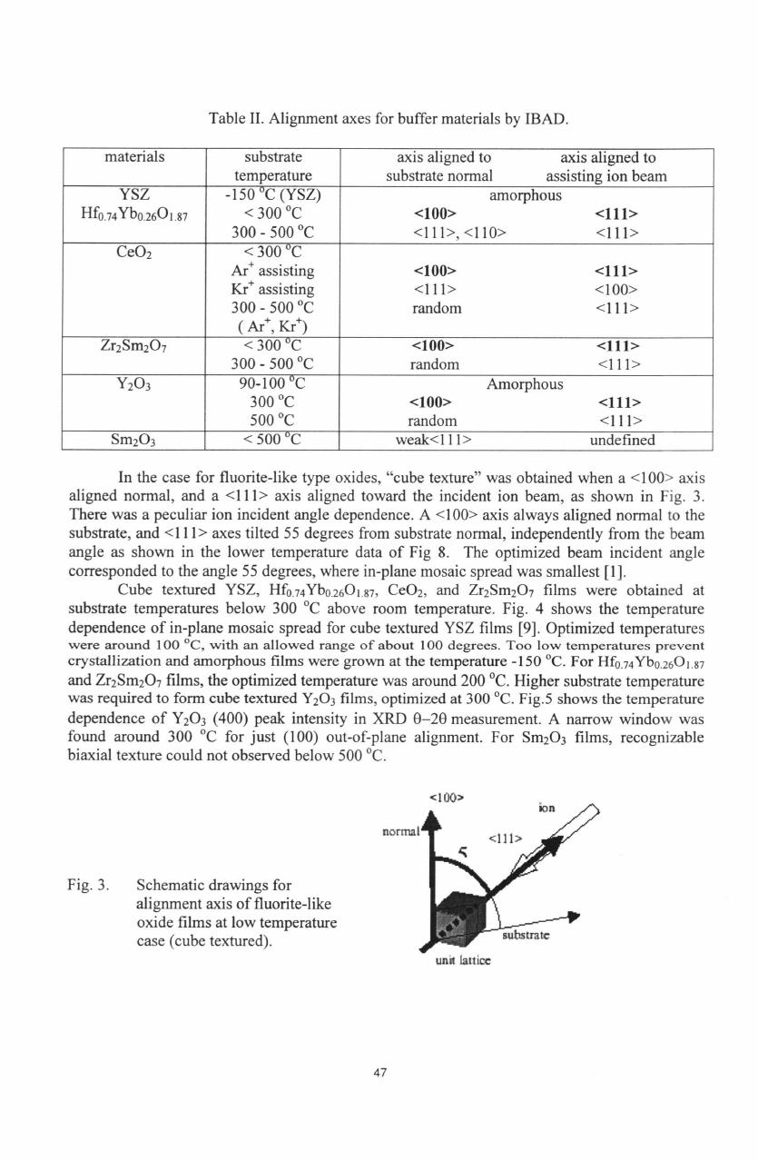
Table
II.
Alignment
axes for
buffer materials
by
IBAD.
In
the
case for
fluorite-like
type
oxides,
"cube
texture" was
obtained
when
a
<100>
axis
aligned
normal,
and a
<111>
axis
aligned
toward
the
incident
ion beam,
as
shown
in
Fig.
3.
There
was
a
peculiar
ion
incident
angle dependence.
A
<100>
axis
always
aligned normal
to
the
substrate,
and
<111>
axes
tilted
55
degrees
from
substrate
normal,
independently
from
the
beam
angle
as
shown
in
the lower
temperature
data
of
Fig
8.
The
optimized
beam
incident
angle
corresponded
to
the
angle
55
degrees,
where
in-plane
mosaic
spread
was
smallest
[1
].
Cube
textured
YSZ,
Hf
0
.
74
Yb
0
.
26
O
1
.
87
,
CeO
2
,
and
Zr
2
Sm
2
0
7
films
were
obtained
at
substrate
temperatures
below
300
0
C
above
room
temperature.
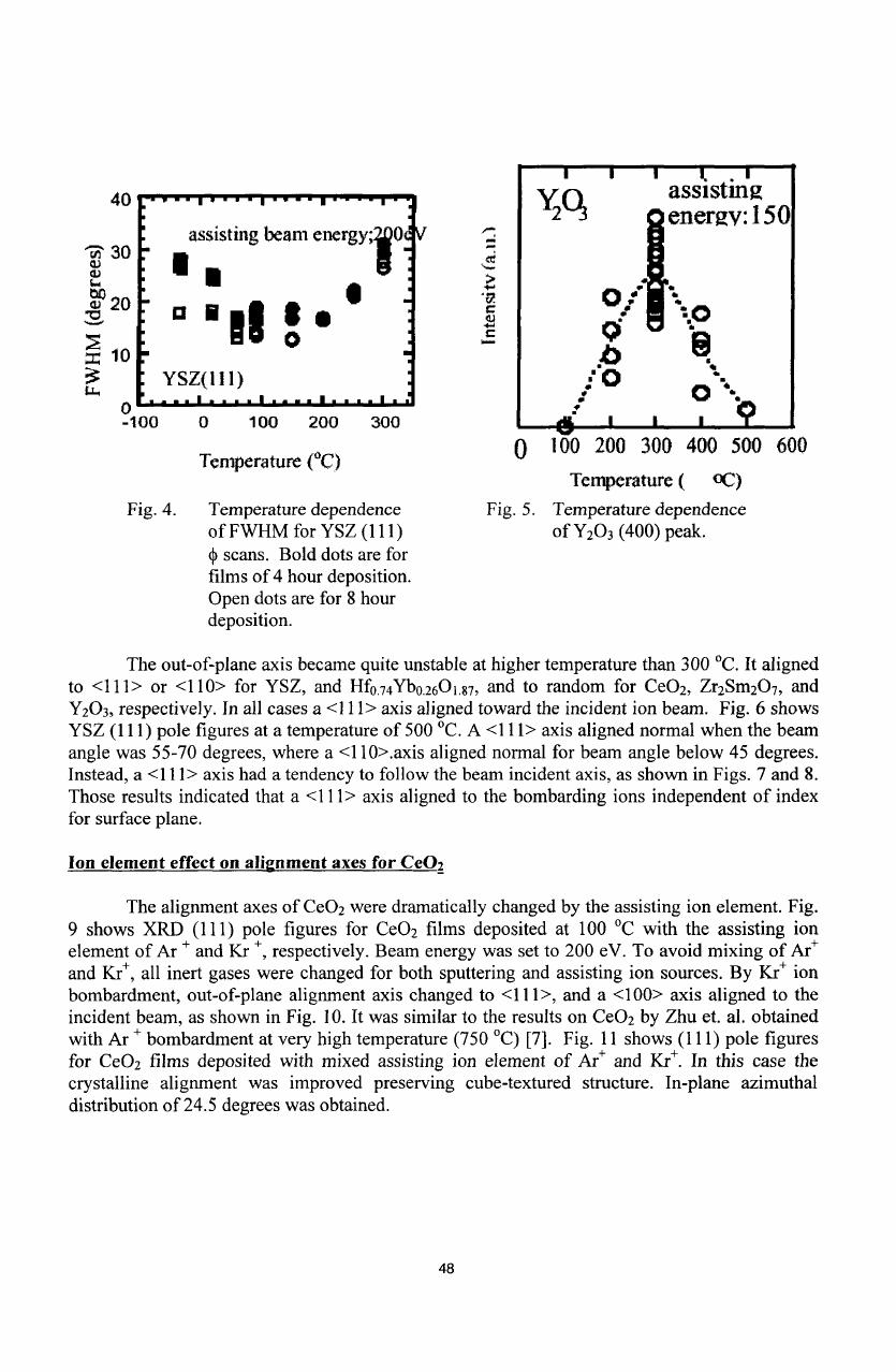
Fig.
4
shows
the
temperature
dependence
of
in-plane
mosaic
spread
for
cube
textured
YSZ
films
[9].
Optimized
temperatures
were
around
100
'C,
with
an
allowed
range
of
about
100
degrees.
Too
low
temperatures
prevent
crystallization
and
amorphous
films
were
grown
at
the
temperature
-150
°C.
For
Hf
0
.
74
Yb
0
.
26
0
1
.8
7
and
Zr
2
Sm
2
0
7
films,
the
optimized
temperature
was
around
200
0
C.
Higher
substrate
temperature
was
required
to
form
cube
textured
Y
2
0
3
films,
optimized
at
300
TC.
Fig.5
shows
the
temperature
dependence
of
Y
2
0
3
(400)
peak intensity
in
XRD
0-20
measurement.
A
narrow
window
was
found around
300
°C
for
just
(100)
out-of-plane
alignment.
For
Sm
2
0
3
films,
recognizable
biaxial
texture
could
not observed
below
500
°C.
<I00>
ion
normal
<111>
Fig.
3.
Schematic
drawings
for
alignment
axis
of
fluorite-like
oxide
films
at
low
temperature
case
(cube
textured).
,ubstrte
uni
lattice
47
materials
substrate
axis
aligned
to
axis
aligned
to
temperature
substrate
normal
assisting
ion
beam
YSZ
-150
°C
(YSZ)
amorphous
HfO.
74
Yb
0
.
26
0
1
.
87
<
300
°C
<100>
<111>
300-500
°C
<l1l>,<ll0>
<111>
CeO
2
<
300
°C
Ar+
assisting
<100>
<111>
Kr+ assisting
<111>
<100>
300
-
500
°C
random
<111>
(
Ark,
Kr+)
Zr
2
Sm
2
0
7
<
300
°C
<100>
<111>
300
-
500
°C
random
<111>
Y
2
0
3
90-100
°C
Amorphous
300
°C
<100>
<111>
500
°C
random
<111>
Sm
2
0
3
<
500
°C
weak<l
11>
undefined
40
'7
3
assisting
beam
energy;O
30 U
20
0
.0
0
z 0
YSZ(1
11)
p
o
4
100
0
100
200
300
1
I i
Temperature
(C)
100
200
300
400
500
600
Temperature
(
DC)
Fig.
4.
Temperature dependence
Fig.
5.
Temperature
dependence
of
FWHM
for
YSZ
(111)
of
Y
2
0
3
(400)
peak.
Sscans.
Bold
dots
are
for
films
of
4
hour deposition.
Open
dots
are
for
8
hour
deposition.
The
out-of-plane
axis
became
quite unstable
at
higher temperature than
300
TC.
It
aligned
to
<111>
or
<110>
for
YSZ,
and
Hf
0 74
Yb
026
O
1
.
87
,
and
to
random
for
CeO
2
,
Zr
2
Sm
2
0
7
,
and
Y
2
0
3
,
respectively.
In
all
cases
a
<111>
axis
aligned toward
the
incident
ion
beam.
Fig.
6
shows
YSZ
(111)
pole
figures
at
a
temperature
of
500
0
C.
A
<111>
axis
aligned
normal when
the
beam
angle
was
55-70
degrees,
where
a
<1
10>.axis
aligned normal for beam
angle
below
45
degrees.
Instead,
a
<111>
axis had
a
tendency
to
follow
the
beam
incident
axis,
as
shown in
Figs.
7
and
8.
Those
results indicated
that
a
<1I1>
axis
aligned
to
the
bombarding
ions
independent
of
index
for
surface
plane.
Ion
element
effect
on
alignment
axes
for
Ce0
2
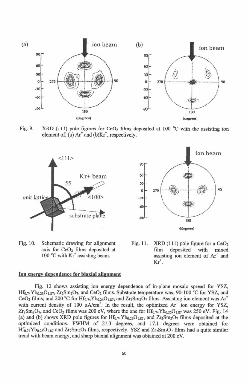
The
alignment
axes
of
CeO
2
were
dramatically changed
by
the
assisting ion
element.
Fig.
9
shows XRD
(111)
pole figures
for
CeO
2
films
deposited
at
100
TC
with the assisting
ion
element
of
Ar
+
and
Kr
+,
respectively. Beam
energy
was
set to
200
eV.
To
avoid
mixing
of
Ar+
and
Kr+,
all
inert
gases were changed
for
both sputtering
and
assisting ion
sources.
By
Kr+
ion
bombardment,
out-of-plane
alignment
axis
changed
to
<111>,
and
a
<100>
axis
aligned
to
the
incident
beam,
as
shown
in
Fig.
10.
It
was
similar
to the
results
on
CeO
2
by
Zhu
et.
al.
obtained
with Ar
+
bombardment
at
very
high temperature
(750
'C)
[7].
Fig.
11
shows
(111)
pole
figures
for
CeO
2
films
deposited
with mixed assisting
ion
element
of
Ar+
and
Kr+.
In
this case
the
crystalline alignment
was
improved preserving
cube-textured
structure.
In-plane
azimuthal
distribution
of
24.5
degrees was
obtained.
48

(a)
(b)
90
30
0
-30
-60
270
90
30
0
-30
-90
(4egrvwl
270
ISO
(depges)
Fig.
6.
YSZ
(111)
pole
figures
for
various
beam
incident angles
at
temperature
of
500
°C,
with
the
beam
incident
angle
of:
(a)
35
0,
and
(b)
55
0,
respectively.
<111
unit
<110>
ion
be
l
substrate
ptane
,i
C0
0
III
60>
40U
20
00
20
40
60
60
Beam
incident angle
(degree)
Fig.
7.
Schematic
drawing for alignment
axis
of
fluorite-like
oxide films
at
high temperature
case.
Fig.
8.
The
relationship
between
the angles
from
normal, for
the incident
ion
axis, and
a
corresponding
<111>
axis.
Bold dotted
line
indicates
where
a
<111>
axis aligned to
the
beam
axis.
49
--
----
X----
90
_
~5oo0_
a
<I11>
axis
I//•am
incident
angle
tI I
I I
(a)
(a)
90
60
30
0
-30
-60
270
-90'
(b)
90
30
-90L
)so
Fig.
9.
XRD
(111)
pole
figures
for
CeO
2
films
deposited
element
of;
(a)
Ar+
and
(b)Kr+,
respectively.
<111>
90•
60
30
0
-30
.60
-90
I
Fig.
10.
Schematic
drawing for alignment
axis
for
Ce0
2
films deposited
at
100
TC
with
Kr+ assisting
beam.
Ion
energy
dependence
for
biaxial
alienment
unit
270
90
at
100
°C
with the assisting
ion
ISO
(d~voes)
Fig.
11.
XRD
(111)
pole figure
for
a
CeO
2
film
deposited
with
mixed
assisting
ion
element
of
Ar+
and
Kr+.
Fig.
12
shows
assisting
ion
energy
dependence
of
in-plane
mosaic
spread
for
YSZ,
Hfo.
74
Ybo.
26
0
1
.
87
,
Zr
2
Sm
2
0
7
,
and
CeO
2
films.
Substrate
temperature
was;
90-100
°C
for
YSZ,
and
CeO
2
films;
and
200
°C
for
Hfo.
74
Ybo.
2
6
0
1
.8
7
,
and
Zr
2
Sm
2
0
7
films.
Assisting
ion
element
was
Are
with current
density
of
100
pA/cm
2
.
In
the
result,
the
optimized
Ar
ion energy
for
YSZ,
Zr
2
Sm
2
0
7
,
and CeO
2
films
was
200
eV,
where
the
one
for
Hfo.
74
Ybo.
26
0
1
.
87
was
250 eV.
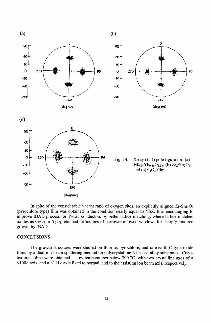
Fig.
14
(a) and
(b)
shows XRD
pole
figures
for
Hfo.
74
Ybo.
26
0
1
.
87
,
and
Zr
2
Sm
2
0
7
films
deposited
at
the
optimized
conditions. FWHM
of
21.3
degrees, and
17.1
degrees
were
obtained
for
Hfo.
74
Ybo.
26
0
1
.
87
and
Zr
2
Sm
2
0
7
films,
respectively. YSZ and
Zr
2
Sm
2
0
7
films
had
a
quite
similar
trend
with
beam
energy,
and sharp
biaxial
alignment
was
obtained
at
200
eV.
50
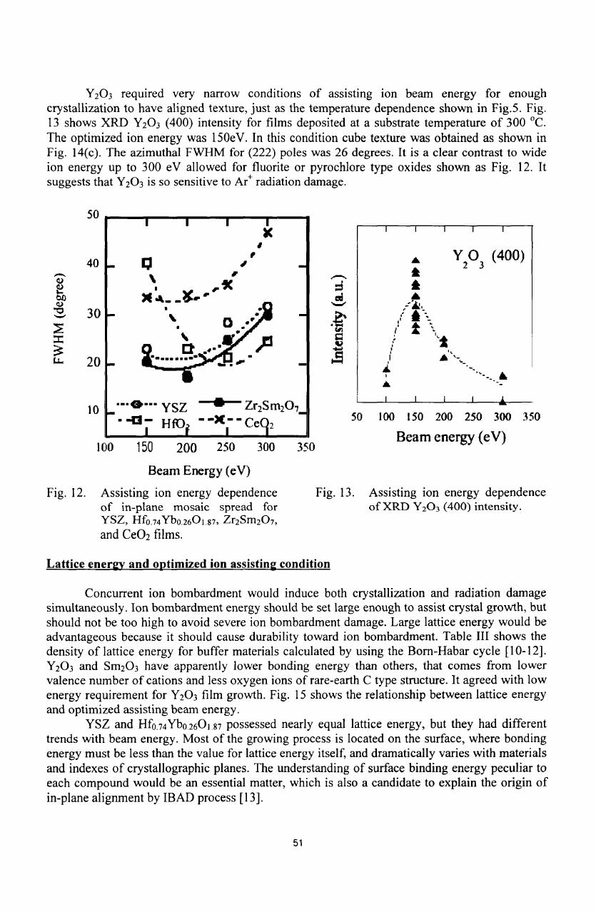
Y
2
0
3
required
very
narrow
conditions
of
assisting
ion
beam
energy
for
enough
crystallization
to
have
aligned texture,
just
as
the
temperature dependence
shown
in Fig.5.
Fig.
13
shows
XRD
Y
2
0
3
(400)
intensity
for
films
deposited
at
a
substrate
temperature
of
300
0
C.
The
optimized
ion energy
was
150eV. In
this
condition
cube
texture was
obtained
as
shown
in
Fig.
14(c).
The
azimuthal
FWHM
for (222)
poles was
26
degrees.
It
is
a
clear
contrast
to
wide
ion
energy
up
to
300
eV
allowed
for
fluorite or
pyrochlore
type oxides shown
as
Fig.
12.
It
suggests
that
Y
2
0
3
is
so
sensitive
to
Ar+
radiation
damage.
I I I I
K
I I I I
I
40
Y
2
Y
3
(400)
323
S
30
-. "
S
20
-'-
10
...
YSZ
-
Zr
2
Sm
2
O_
i i i I
--
HoIO
-_
-e
50
10
150
200
250
300
350
J
eg
Beam
energy
(eV)
100
150
200
250
300
350
Beam
Energy
(eV)
Fig.
12.
Assisting
ion
energy
dependence
Fig.
13.
Assisting
ion energy
dependence
of
in-plane
mosaic
spread
for
of
XRD
Y
2
0
3
(400)
intensity.
YSZ,
Hfo.
74
Ybo.
26
0
1
.87,
Zr
2
Sm
2
O
7
,
and
CeO
2
films.
Lattice
energy
and
optimized
ion
assisting
condition
Concurrent
ion
bombardment
would induce
both
crystallization
and
radiation
damage
simultaneously.
Ion
bombardment
energy
should
be set large
enough
to
assist
crystal
growth,
but
should not
be
too
high
to
avoid
severe ion
bombardment
damage.
Large lattice energy
would
be
advantageous
because
it
should
cause
durability toward
ion
bombardment.
Table
III
shows
the
density
of
lattice energy
for
buffer
materials calculated
by
using
the
Bom-Habar
cycle
[10-12].
Y
2
0
3
and
Sm
2
0
3
have
apparently
lower
bonding
energy
than
others, that
comes
from lower
valence
number
of
cations
and
less
oxygen
ions
of
rare-earth
C
type
structure.
It
agreed with
low
energy
requirement
for
Y
2
0
3
film
growth. Fig.
15
shows
the
relationship
between
lattice
energy
and
optimized
assisting beam
energy.
YSZ
and
Hf
0
.
7
4
Yb
0
2601.87
possessed
nearly
equal
lattice
energy,
but they
had
different
trends with
beam
energy.
Most
of
the growing
process
is
located on the
surface,
where
bonding
energy
must
be
less
than
the
value
for
lattice
energy
itself,
and
dramatically
varies
with
materials
and
indexes
of
crystallographic
planes.
The
understanding
of
surface
binding
energy
peculiar
to
each
compound
would
be an
essential
matter,
which
is
also
a
candidate
to
explain
the
origin
of
in-plane
alignment
by
IBAD process
[13].
51
(a)
(b)
0
270
/ : ,/
(degree;)
270
0
jt
90
(0
30
0
30
-60
0
270
(A
I
90
-
K
/
(degreel
N
90
Fig.
14.
X-ray
(111)
pole
figure
for;
(a)
Hfo.
74
Yb
02
6
0
1
.
87
,
(b)
Zr
2
Sm
2
0
7
,
and
(c)Y
2
0
3
films.
-
iRO
(cdegreez)
In
spite
of
the
considerable
vacant ratio
of
oxygen
sites, an
explicitly aligned
Zr
2
Sm
2
0
7
(pyrochlore
type)
film
was
obtained
in
the
condition
nearly
equal
to
YSZ.
It
is
encouraging
to
improve
IBAD
process
for
Y-123
conductors
by
better
lattice
matching,
where lattice
matched
oxides
as
CeO
2
or
Y
2
0
3
,
etc.
had
difficulties
of
narrower
allowed windows
for sharply
textured
growth
by IBAD.
CONCLUSIONS
The
growth
structures
were
studied
on fluorite,
pyrochlore,
and
rare-earth
C
type
oxide
films
by
a
dual-ion-beam
sputtering
method
on
polycrystalline
Ni-based alloy
substrates.
Cube-
textured
films
were obtained
at
low
temperatures
below
300
"C,
with
two
crystalline
axes
of
a
<100> axis,
and
a
<111>
axis
fixed
to
normal, and
to the
assisting
ion beam
axis,
respectively.
52
90
60
30
0
-30
.60
-90,
(c)
90
60-
30-
-90-
•)
-9u
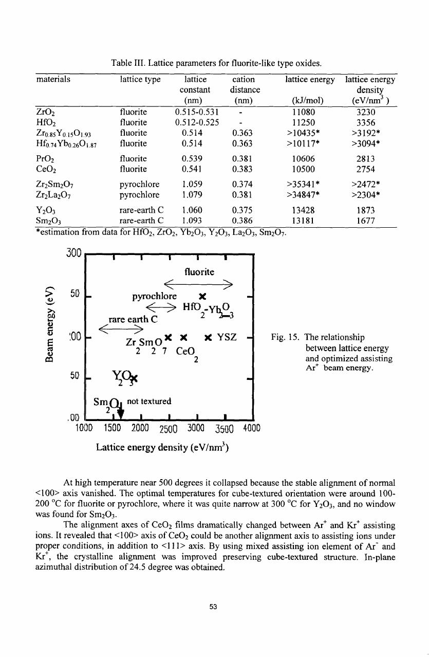
Table
III.
Lattice parameters for fluorite-like
type
oxides.
materials
lattice
type
lattice
cation
lattice
energy
lattice
energy
constant
distance
density
(nm)
(nm)
(kJ/mol)
(eV/nm
3
)
ZrO
2
fluorite
0.515-0.531
-
11080
3230
HfO
2
fluorite
0.512-0.525
-
11250
3356
Zr085Y01501.93
fluorite
0.514
0.363
>10435*
>3192*
Hf
0
.
74
Yb
026
O
1 8
7
fluorite
0.514
0.363
>10117*
>3094*
PrO
2
fluorite
0.539
0.381
10606
2813
CeO
2
fluorite
0.541
0.383
10500
2754
Zr
2
Sm
2
0
7
pyrochlore
1.059
0.374
>35341*
>2472*
Zr
2
La
2
O
7
pyrochlore
1.079
0.381
>34847*
>2304*
Y
2
0
3
rare-earth
C
1.060
0.375 13428
1873
Sm
2
0
3
rare-earth
C
1.093
0.386
13181
1677
*estimation
from
data
for
HfO
2
,
ZrO
2
,
Yb
2
0
3
, Y
2
0
3
,
La
2
0
3
, Sm
2
0
7
.
300
50
100
P-11I
1000
1500
2000
2500
3000
3500
Fig.
15.
The
relationship
between lattice
energy
and
optimized
assisting
Ar+ beam
energy.
4000
Lattice
energy
density
(eV/nm
3
)
At
high temperature
near
500
degrees
it
collapsed
because
the
stable
alignment
of
normal
<100> axis
vanished.
The
optimal temperatures
for cube-textured
orientation
were
around
100-
200
TC
for
fluorite
or
pyrochlore,
where
it
was
quite
narrow
at
300
TC
for
Y
2
0
3
,
and
no
window
was
found for
Sm
2
0
3
.
The
alignment
axes
of
CeO
2
films
dramatically
changed
between
Ar+ and
Kr+
assisting
ions.
It
revealed
that <100>
axis
of
CeO
2
could
be
another
alignment
axis
to
assisting
ions
under
proper conditions,
in
addition
to
<1I1>
axis.
By
using
mixed
assisting
ion
element
of
Ar-
and
Kr+,
the
crystalline
alignment
was
improved
preserving
cube-textured
structure.
In-plane
azimuthal
distribution
of
24.5
degree
was obtained.
53
Co
I-
fluorite
pyrochlore
X
<-
HfC
-i
2
rare
earth
C
.<
>z
X
X
YSZ
7
Zr
SmO
YS
2
2 7
CeO
2
Sn2O
not
textured
I2I I
The
assisting
ion
energy
dependence
was
discussed
in
connection with
lattice
energies
for
these
oxide crystals.
For
fluorite
or
pyrochlore,
the
optimized
energy
was
200-250
eV,
where
low
energy
(150eV)
ion
bombardment
with
narrow
window
was
required
for
crystallization
of
Y
2
0
3
films.
The
calculated
lattice
energy suggests
that rare-earth
C
type oxides
(Y
2
0
3
,
Sm
2
0
3
)
are
so
sensitive
to
ion
radiation
damage
because
of
insufficient
bonding
energy.
Explicitly
aligned
pyrochlore
type oxide
(Zr
2
Sm
2
O
7
)
films
are
obtained
with azimuthal
FWHM
of
17.1
degrees,
in
the
condition
nearly
equal
to
the
one for YSZ.
It
is
encouraging
to
improve
IBAD
process
for
Y-123
conductors
by
better
lattice
matching
of
pyrochlore oxides,
where
other
candidates
as
CeO
2
or
Y
2
0
3
films have yet
difficulties
to
optimize
conditions
of
IBAD.
REFERENCES
I.
Y.
lijima,
K.
Onabe,
N.
Futaki,
N.
Tanabe,
N.
Sadakata,
0.
Kohno,
and
Y.
Ikeno,
IEEE
Trans Appl. Supercond.
3,
1510
(1993).
2.
Y.
Iijima,
M.
Hosaka,
N.
Tanabe, N.
Sadakata,
T.
Saitoh,
0.
Kohno,
and
K.
Takeda,
J.
Mater
Res.
13,
3106
(1998).
3.
S.
R.
Foltyn,
P.
N.
Arendt,
C.
Dowden,
R.
F.
DePaula,
J.
R.
Groves,
J.
Y.
Coulter,
Q.
Jia,
M.
P.
Maley,
and
D.
E.
Peterson,
to be
published
in
IEEE Trans. Appl. Supercond.
9,
(1999).
4.
C. P.
Wang,
K.
B.
Do,
M.
R.
Beasley,
T.
H.
Geballe,
and R.
H.
Hammond,
Appl. Phys. Lett.
71,
2955
(1997).
5.
M.
Hosaka,
Y.
lijima,
N.
Sadakata,
T.
Saitoh,
0.
Kohno, and
K.
Takeda,
Advances
in
Superconductivity
vol.
9,
ed.
S.
Nakajima
and
M.
Murakami,
p.749,
Springer, Tokyo,
1997.
6.
J. J.
Cuomo,
S.
M.
Rossnagel,
and
H.
R.
Kaufman,
Handbook
of
Ion-Beam
Processing
Technology,
p.
170,
Noyes,
New
Jersey,
1989.
7.
S.
Zhu,
D.
H.
Lowndes,
J.
D.
Budai,
and
D.
P.
Norton,
Appl.
Phys.
Lett.
65,
2012
(1994).
8.
V.
Betz,
B.
Holzapfel,
D.
Raouser,
and
L.
Schultz,
Appl. Phys.
Lett.
71,
2952
(1997).
9.
Y.
lijima,
M.
Kimura,
N. Tanabe,
N.
Sadakata,
T.
Saitoh,
and
K.
Takeda:
Advances
in
Superconductivity,
Vo
I .
11,
eds.
N.
Koshizuka
and
S.
Tajima,
p.785,
Springer,
Tokyo,
1999.
10.
L.
R.
Morss,
Chem.
Rev.
76, 827
(1976).
11.
D.
D.
Wagmann,
et.
al.,
NBS
Technical
Note 270,
Selected
Values
of
Chemical
Thermodynamic
Properties,
(U.S.
Gov.
Printing
Office,
1981).
12.
C.
E.
Moore,
Analysis
of
Optical
Spectra,
WSRDS-NBS
34,
(National
Bureau
of
Standards,
1971).
13.
K.
G.
Resslar,
N.
Sonnenberg,
and M.
J.
Cima:
J.
Am. Ceram.
Soc.
80,
2637
(1997).
54
