Reliability and Performance of Pseudomorphic Ultraviolet Light Emitting Diodes on Bulk
Aluminum Nitride Substrates
James R. Grandusky
1
, Yongjie Cui
1
, Mark C. Mendrick
1
, Shawn Gibb
1
, and Leo J. Schowalter
1
Crystal IS, 70 Cohoes Avenue, Green Island, NY 12183, U.S.A.
ABSTRACT
Reliability and performance of ultraviolet light emitting diodes have suffered due to the high
dislocation density of the AlN and high Al-content Al
x
Ga
1-x
N layers when grown on foreign
substrates such as sapphire. The development of pseudomorphic layers on low dislocation
density AlN substrates is leading to improvements in reliability and performance of devices
operating in the ultraviolet-C (UVC) range. One major improvement is the ability to operate
devices at much higher current densities and input powers than devices on sapphire substrates.
This is due to the better thermal properties and lower dislocation density of devices on AlN
substrates. Devices with active area of 0.001 cm
2
emitting at ~265 nm have been measured for
their reliability and change in power output over time at input currents of 20 mA (20 A/cm
2
), 100
mA (100A/cm
2
) and 150 mA (150 A/cm
2
). When operating at currents of 20 mA over 3500
hours of consecutive operation has been demonstrated with typical decay of ~27% over the 3500
hours. Extrapolating the decay with a linear fit gives a L50 (time to 50% of initial power) of
~5000 hrs. However it is desirable to be able to model the decay to better understand the
kinetics and better understand the mechanisms. In order to do this, the lifetime at 20 mA and
100 mA were modeled using an exponential decay function, square root transformation and a log
transformation to both be able to fit the experimental data and predict future performance.
INTRODUCTION
Ultraviolet disinfection is becoming very important as an efficient means of providing
disinfection to water, air and surfaces without the use of chemicals. This requires a light source
that is emitting in the ultraviolet-C (UVC) range (<300 nm) for efficient disinfection due to a
peak in DNA absorption at ~ 265 nm
1
. Traditionally, mercury lamps are used, however these
suffer the disadvantages of short lifetimes, slow start up, and the use of toxic mercury which can
be a hazard if the bulb is broken and leads to problems with disposal. Light emitting diodes
(LEDs) have the capability of high efficiencies, fast start up which can be synchronized with
water flow, long lifetimes, variable wavelengths, and no toxic materials.
However, currently devices are fabricated from Al
x
Ga
1-x
N layers on sapphire substrates
which lead to a high dislocation density and thus low efficiencies and short lifetimes
2
. Bulk AlN
substrates offer several advantages over growth on sapphire, including low lattice and thermal
mismatch between the substrate and the device layers. In addition, pseudomorphic growth of
Al
x
Ga
1-x
N with x>0.6 can be obtained resulting in device layers with low dislocation densities,
low resistivities, and atomically smooth surfaces
3
.
Mater. Res. Soc. Symp. Proc. Vol. 1195 © 2010 Materials Research Society 1195-B03-04
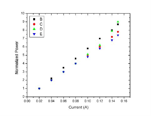
Figure 1. Performance of pseudomorphic UVC LEDs on bulk AlN substrates when driven to
high currents for 4 different devices. The Y axis (output power) is normalized to 20 mA and
shows linear increase in output power up to 150 mA drive current.
EXPERIMENT
Epitaxial growth was carried out as discussed previously
3
. The device structure consisted of
an n-type Al
x
Ga
1-x
N layer, a 5 period multiple quantum well, an electron blocking layer, and a p-
type GaN contact layer. Devices were processed using standard LED processing with a mesa
diameter of 350 µm. The devices are flip chip mounted to an AlN submount and packaged in
TO-8 and surface-mounted design (SMD) packages.
For testing of the diodes, the packaged devices were mounted on a pin fin anodized Al heat
sink (40 mm x 40 mm) with forced convection cooling which had an experimentally validated
theoretical thermal resistance of 2.5
o
C/W. With an applied forward bias, the output power was
measured in a calibrated integrating sphere. For lifetime measurements a photodiode was used
to measure the output power of each device.
DISCUSSION
Initial measurements were carried out on the devices at different input currents from 20 mA
to 150 mA. At each step, the system (device and heat sink) was allowed to achieve thermal
equilibrium and the output power was stable. The output power was then normalized to the
power at 20 mA and plotted versus forward current as shown in figure 1. In each device, the
increase in power at currents up to 150 mA is linear with no roll off or thermal effects. The
forward voltage of the devices is quite high and typically 20 V at 150 mA forward current
resulting in an input power of 3 W. The forward voltage is expected to become lower as the n
and p contact metallization is improved.
In order to test the potential of the devices at elevated currents, devices were tested at
currents greater than 150 mA without letting the device reach thermal equilibrium (quasi-cw).
figure 2 shows the results with an output power of 1.3 mW at 400 mA of current with a peak
wavelength of 258 nm.
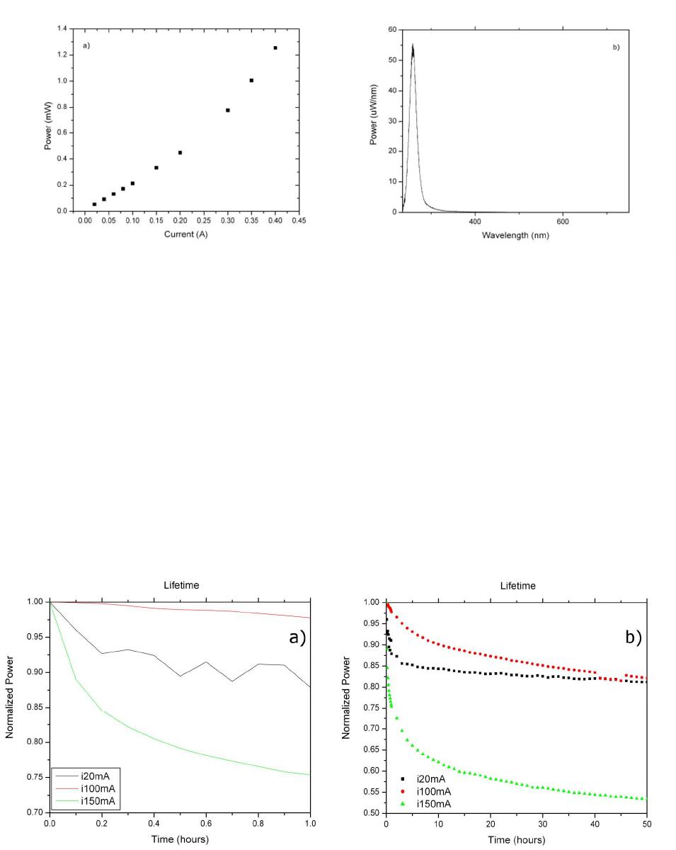
Figure 2. Performance of pseudomorphic UVC LEDs on bulk AlN substrates when driven to a
forward current of 400 mA. The inset shows the spectra of the device at 400 mA with a peak
wavelength of 258 nm.
In addition to improved performance of the devices, an important feature of the
pseudomorphic LEDs is the reliability. It is expected that the low dislocation density in the
substrates will lead to increased reliability and increased lifetimes over devices fabricated on
sapphire substrates. Lifetime measurements were carried out at input currents of 20 mA, 100
mA, and 150 mA. For measurements at 20 mA no heat sinking was used and the devices were
suspended in air. However for higher currents, such as 100 and 150 mA, power inputs of up to 3
W necessitated the use of a heat sink.
Reliability measurement at each current showed three distinct mechanisms for power decay.
The first mechanism was temperature related and due to the device reaching thermal equilibrium.
This was reversible, i.e. if the device was turned off and allowed to cool the power would
initially recover, followed by a rapid drop until thermal equilibrium was reached. This
degradation is shown in Figure 3a. For the 20 mA case, the power drops fast initially due to the
Figure 3. Power decay during the a) first hour of testing and b) first 50 hours for different drive
currents.
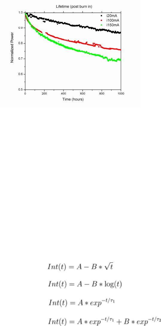
Figure 4. Power decay during the first 1000 hours of testing for different drive currents.
fact that there is no external heat sinking of the devices. For 100 mA very little heating is
observed due to the adequate heat sinking for the power input. At 150 mA however there is a
considerable rise in junction temperature leading to severe power decay in the first several
minutes of operation. The second decay mechanism is burn in, shown in figure 3b. It is unclear
exactly what the mechanism of this decay is, but it could be related to impurity diffusion in the
material
4
or further alloying of the contacts. When run in pulsed mode with low duty cycle the
decay is much slower indicating a stronger dependence on junction temperature as opposed to
current density.
After burn in there is a slow decay in power over time. The power decay is faster for higher
currents as expected, but it is unclear if this is thermally related or current density related. This
decay is shown in figure 4. As the decay is relatively slow, it becomes important to be able to
predict the lifetime of devices based on as little experimental data as possible. In order to do
this, devices were allowed to operate at 20 mA for 3500 hours and at 100 mA for 2000 hours.
The data from 100, 500, 1000, 1500, 2000, 2500, and 3000 hours was fitted and used to predict
the L50 of the devices at each step. Figure 5 shows the fitted L50 for devices operated at 20 mA
and 100 mA as a function of time fitted by the following functions:
(1) Square root
(2) Logarithmic
(3) One channel exponential decay
(4) Two channel exponential decay
The two channel exponential decay and the square root fit are able to accurately fit the data
with R
2
values of 0.98 while the log fit shows a very good fit for the 100 mA data with a R
2
of
0.98 but a value of 0.92 for the 20 mA data. This is believed to be due to the lack of heat sinking
of the devices operated at 20 mA and the rapid initial drop. The one channel exponential decay
has the worst fit for both cases with R
2
values of 0.86 and 0.75 for the 20 mA and 100 mA cases
respectively. However, looking at the fitted values of L50, the predicted lifetime continues to
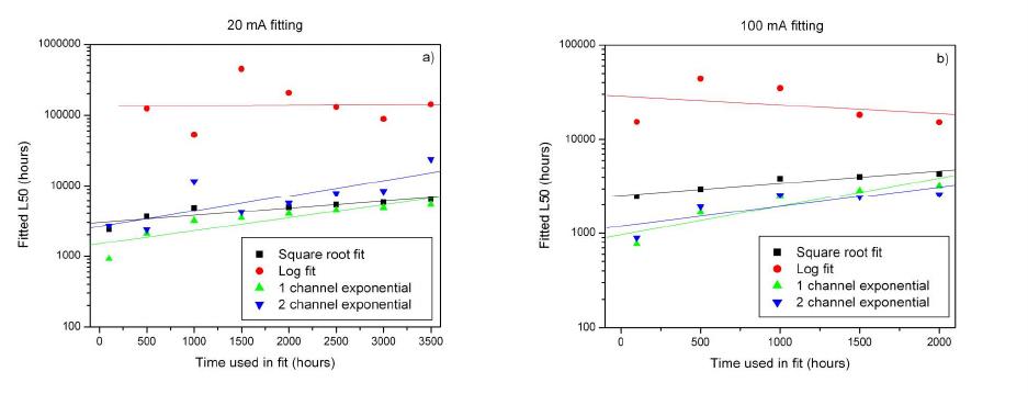
Figure 5. Fitted L50 as a function of time used in fit for 4 different models at a) 20 mA and b)
100 mA.
increase for the fits using the square root and exponential decay functions. However for the log
fit the value of L50 predicted after a short time is similar to the predicted value after a long time.
It appears that fitting the data to a log fit after only a few days worth of data gives the best
method of estimating the L50 with limited data; however we are continuing to collect data and
analyze the fitting functions to determine the best way to predict the L50.
The exponential
5
and square root
6
fits are typically used in the fitting of LED
degradation, and are able to provide adequate fits to the data here, but are not good at predicting
the lifetime. The reason for the breakdown in the prediction using the exponential functions is
due to the fact that this function is forced to go to zero and thus typically underestimates the
lifetime. This can be solved by adding a constant to the fit which will improve the fit of the data,
however this constant is not helpful in estimating the lifetime of the device (since it makes the
lifetime infinite). The logarithm fit has been used for modeling hot carrier injection and
electromigration in electronic devices and used to predict the lifetime of the devices over several
orders of magnitude with as short a measurement time as possible
7
. While hot carrier injection is
not relevant to light emitting diodes, the method of predicting lifetimes is similar and attempts to
relate this to a physical process in the material is currently underway.
CONCLUSIONS
The use of pseudomorphic layers grown on bulk AlN substrates has lead to the improved
performance and reliability of UVC LEDs. In addition to the improved performance at high
current densities, device reliability is much improved over devices grown on foreign substrates.
Devices have currently been operating for 3500 hours at 20 mA and 2000 hours at 100 mA
without reaching L50 and are currently still operating. This has lead to an effort to be able to fit
the decay of the power and be able to accurately predict the L50 value with as little data as
possible. The data was fitted to square root, logarithmic, and one and two channel exponential
decay functions to obtain the best function to predict the L50 values with a limited amount of
measured data. The logarithmic function was chosen as the best based on the current predictions
as the other fits continue to predict longer L50 values as more data is collected. With as little as
100 hours of data the logarithmic fit obtains similar values as to that obtain after 2000 hours at
100 mA. More data is currently being collected and analyzed to further validate this after the
devices reach their L50 values.
ACKNOWLEDGMENTS
This work was partially supported by an ATP grant (administered by NIST).
REFERENCES
1. EPA Document # 815-D-03-007
2. A. Khan, S. Hwang, J. Lowder, V. Advirahan, and Q. Fareed, Reliability Physics Symposium,
2009 IEEE International, 89, (2009).
3. J. R. Grandusky, J. A. Smart, M. C. Mendrick, L. J. Schowalter, K. X. Chen, and E. F.
Schubert, J. Cryst. Growth 311, 2864 (2009).
4. C.G. Moe et al. Reliability Physics Symposium, 2009 IEEE International, 94 (2009).
5. O. Ueda, 1996 “Reliability and Degradation of III-V Optical Devices” Artech House, Inc.
Norwood, MA, pgs. 279-281.
6. S. Sawyer, S. L. Rumyantsev, M. S. Shur, Solid State Electronics 52, 968, (2008).
7. Keithley Instruments Inc., HCI White Paper, (2001).
